I see another picture of cavitation damage, just inside the pump inlet.
> The water boils due to the low pressure right at the suction
> opening and along the face of the vanes.
> Coolant boiling temperature AND pressure determine boiling point.
> So an effective system can loose pressure and begin to cavitate the
> pump. Even stock engines can do this. In a cast iron housing it
may take
> some long time for this kind of damage to become obvious. In an
aluminum
> housing, damage can be sudden. The damage may eliminate some of the
> cavitation through reducing performance, but overall system
performance will
> suffer from a reduction in GPM.
> Sharp edges should be removed from the pump cavity. This
will increase
> pump performance and raise the GPM where cavitation takes place.
>
> It is no accident that the lower radiator hose on every car is bigger
> than the upper radiator hose. The lower hose is the water
pump inlet.
An effort is made to provide coolant to the suction side of the
pump at the
> highest volume and pressure possible. This, so the minimum amount of
> pump possible can do the job. Few cars have way too much water pump
> installed from the factory.
> >
> Raising the boiling point with a higher pressure cap setting helps.
> Using higher boiling point chemicals in the coolant works.
> Slowing the pump a bit works. And restricting pump output works.
If the
> restriction is down stream from the block, then pressure inside
the block
> will be slightly higher, and so, the boiling point inside the block.
> >
> I use a 5/8" restriction on the outlet of the thermostat housing.
> I use a 10% ethylene glycol and a bottle of Red Line Water Wetter.
the crank pulley is from racing beat, and is smaller than stock.
We shift
> at 9,600 RPM. No cooling grooves in the rotor housing. No cavitation
> damage to an aluminum pump and housing in 15 years of racing. No
cracks
around the plug holes. Never an overheat problem. 244.8 HP at
9,400 RPM.
>
> Lynn E. Hanover
>
> Water outlet with 5/8" restricter welded on.
> The clutch discs are Lamar Engineering/Tilton
>
> I would not use that disk on a street car as Robin would complain
> if she had to drive it :) No springs.
>
> I suspect a lot of damage people attributing to caviatation is
> caused by low water.
> I can't imagines the Mazda engineers designing something that
> cavatates in our rev range.
> >
> > Paul Lamar
> >
>
>
>
> Lynn, how many pounds of pressure/cap?
> Steve Beckham
>
>I use a 16 pound lever cap, but Stant makes caps up to 32 pounds. *
>
>Lynn E. Hanover
>
Lynn
Just so I got this correct. It sounds like you are pulling the cooler
water from the bottom of the radiator into the pump and from the pump
into the engine block and then it exits the block back into the top of
the radiator through a smaller size hose. I don't know the orientation
of your radiator whether it is stock straight up or laying at an angle.
I am curious as to where and how you located the pressure cap.
Doug in Japan
The restrictor is on the water outlet, and the top hose is the same size
as a street Mazda. The radiator is a Griffin double pass aluminum. 3" by
19" by 31" Two rows of 1 1/4" tubes. Both inlet and outlet on the
passenger side.
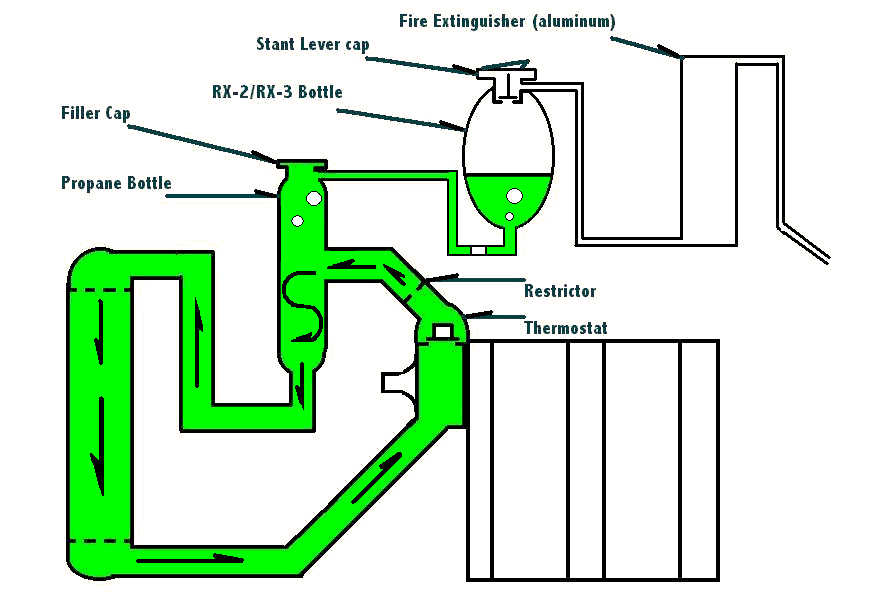
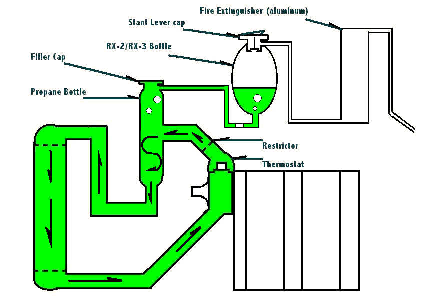
Here is a picture of a cooling system that has worked for me since 1980.
I added the Rol-air-trol. A home made version of a air/water separator.
I used to manufacture heat transfer packages that used a giant version.
I thought Bell and Gosset made those but now I don't see one in their
catalogue. When pumping hot water around a building, you must remove all
of the air from the loop. When air goes through a pump, it expands
violently (cavitates) at the pump inlet and may damage the pump, and it
makes an awful noise at the pump, and going through fin tube cabinets in
each room. Nothing is as funny to school kids as a fin tube cabinet that
sounds like it is having a diarrhea attack. So air in the loop is just
not allowed. The air removing device helped me get the air out quickly
without hurting the engine, as my system may be drained often. It is
difficult to remove air from the rotary when it is level. More so if it
is not level. The rest of the system is what you would have found on
every RX-2 and RX-3. The pressure bottle is kept 1/3 full of coolant.
When air is delivered to the pressure bottle, it pops to the top and
only airless coolant can be forced back into the system when a
temperature/volume change occurs. In two or three heat cycles the system
will be solid coolant. The bottle must be refilled after each heat
cycle, but not over 1/3 full. I have a Shrader valve on my bottle, so I
can be at relief pressure before the engine starts. Probably not
required for airplanes. You could also add the pressure gage on or close
to the bottle for easy reading, and or, a gage on the dash to view
coolant pressure. The racing organizations require that catch tank, but
there is never anything in it.
I used a stock RX-2 pressure bottle, but a better choice would be an
aluminum aftermarket bottle to get a good selection of cap pressures.
The pressure cap is on the bottle. Not on the swirl pot. That cap is
solid and used to fill the system.
Lynn E. Hanover
--
The Rotary Engine NewsLetter. Powered by Linux.
ACRE NL web site.
http://www.rotaryeng.net
Youtube key word UTUBPLEASE
Copyright 1998-2008 All world wide rights reserved.