Paul, Sandy et. al., I have a glass goose project, and due to major
modifications that I plan on making in order to address what I consider major
short-comings, I will no longer be allowed to call it as such. It is now
called a Merganzer. I'm not going to address these changes, as they have
already been posted on the Seahawk, Glass Goose builders web-site. I will,
however, join in on the current discussion on cooling this beast. This
assumes we are working with a liquid-cooled engine.
But first let me share with everyone a recent experience. Last week-end I
went with a fellow EAA member to Plymouth, Massachusetts to help him ferry
his recently purchased RV-9A back home to Zephyrhills, Florida. A really
nice airplane. It has an Eggenfellner Subaru engine (165 H.P., 4 cylinder)
in it. It ran flawlessly, in spite of what I would consider a less than ideal
cooling con- figuration. Let me explain. The heat-exchangers were too small
(Core Area: 5.5"x7.0"x3.0"=115.5 cu. in.x2 H.E.'s=231.0 cu. in.
/ 165 H.P.= 1.40 cu. in. per H.P.), the ducts leading to the heat-exchangers
face did not have a well shaped trumpet diffuser, they were not sealed to
the heat-exchangers, nor were they sealed to the cowl-openings; not what is
recommended in "How To Cool A Wankel". In spite of all this, they did an
adequate job of cooling this engine for 1,200 miles or 8 hours of run time
during 2 days of travel.
I did say "adequate job of cooling" not "great job of cooling". Let me
explain. At 4,800 RPM's (@ engine) the water temp ran about 210*F-215*F. We
were told not to exceed 230*F. So, based on this information, we were OK.
However, I don't feel comfortable with water temps over 200*F. At my
insistence, the owner reluctantly agreed to reduce the throttle to 4,500
RPM's and we then saw water temps from 197*F-200*F. This made me feel more
comfortable. Little by little the owner advanced the throttle until we saw
water temps of 200*F- 205*F @ 4,600 RPM's - 4,700 RPM's: a compromise I
guess. We left it there and saw 148 MPH-150 MPH cruise with no problems.
Now, I'll stick my neck out a little. I know that most of you believe a
thin, wide heat-exchanger will cool better than a compact, thick one. Maybe
that is so; but, in our Seahawks, Glass Goose, Merganzer airplanes, we don't
have room for a wide, thin heat-exchanger. And since I have witnessed a
poorly designed cooling system using compact, thick heat-exchangers do an
adequate job of cooling, I suggest that this is the approach to be taken
with our particular aircraft. I also did some research on heat-exchanger
core-volume requirements. I measured the radiator cores of a Toyota P/U, a
Toyota 4-Runner, a Ford F-350 P/U, and last but not least, the P-51 Mustang.
Then I compared the volume of each core (in cu. in.) to the rated H.P. of
each engine. What I found was a range of 3.4 cu.in. to 3.7 cu.in. of core
per H.P. The average was about 3.5 cu.in. per H.P. Slightly more than 3.0
cu.in. per H.P. recommended, but not by very much. Now for the argument of
thin versus thick cores. While I will not disagree that a wide, thin
heat-exchanger works better than a compact, thick one (as far as cooling
efficiency); what about cooling drag?
If you have a wide, thin core, then you are using a greater volume of air
through the heat-exchanger. More air...more cooling drag. What's your
opinion? Also, I am sure that a 2 inch deep core will have better cooling
efficiency than a 4 inch deep core, but, I am of the opinion that, while not
ideal, the rear 2 inches of a 4 inch deep core is doing some cooling. The
evidence of this is the Eggenfellner Subaru engine in the aforementioned
RV-9A. If space is a major factor (which is a fact in our planes), then why
not design a system using compact, thick heat-exchangers which can be
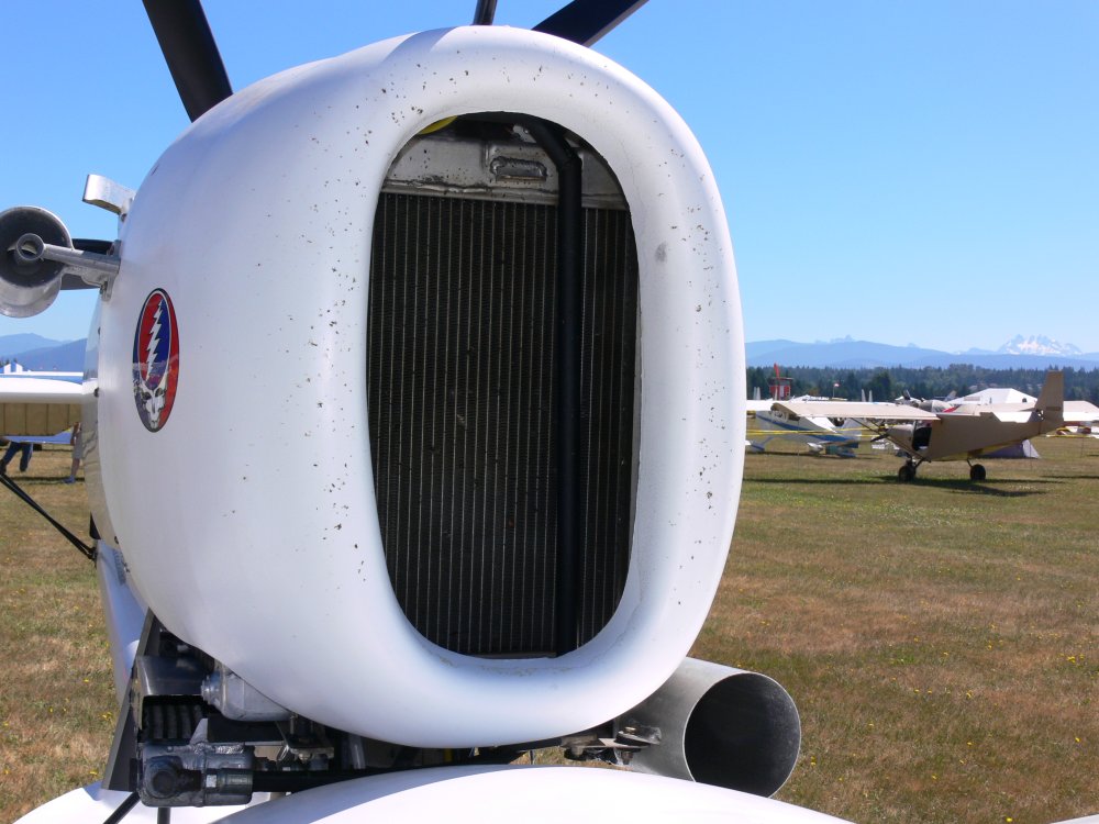
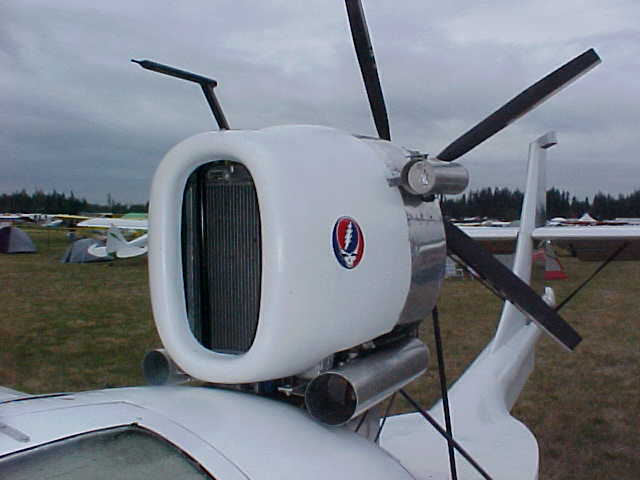
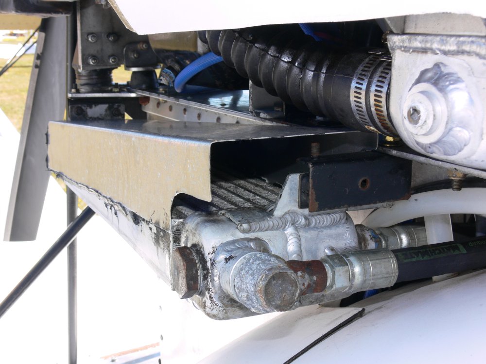
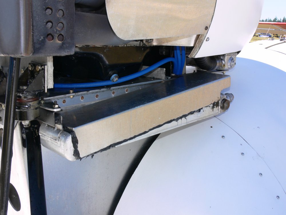
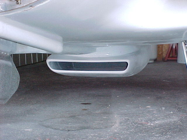
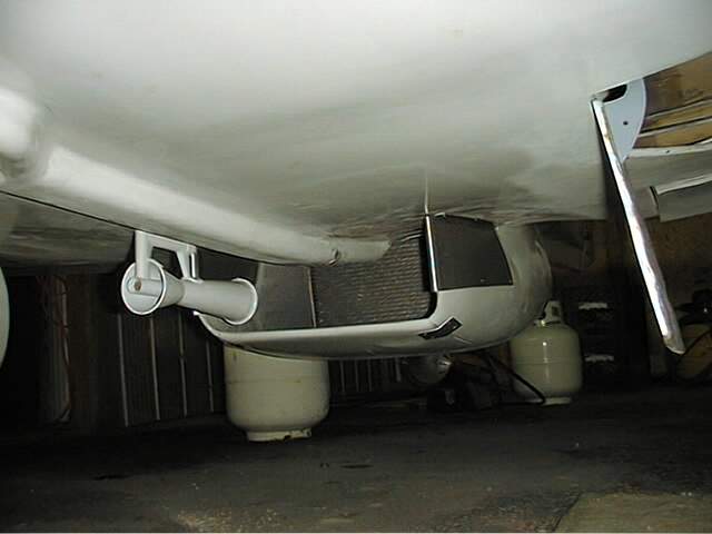
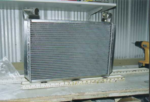
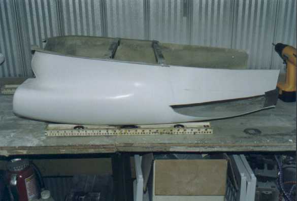
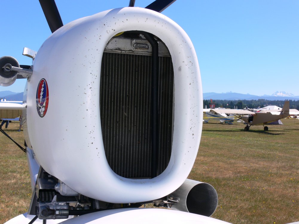
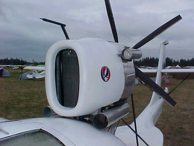
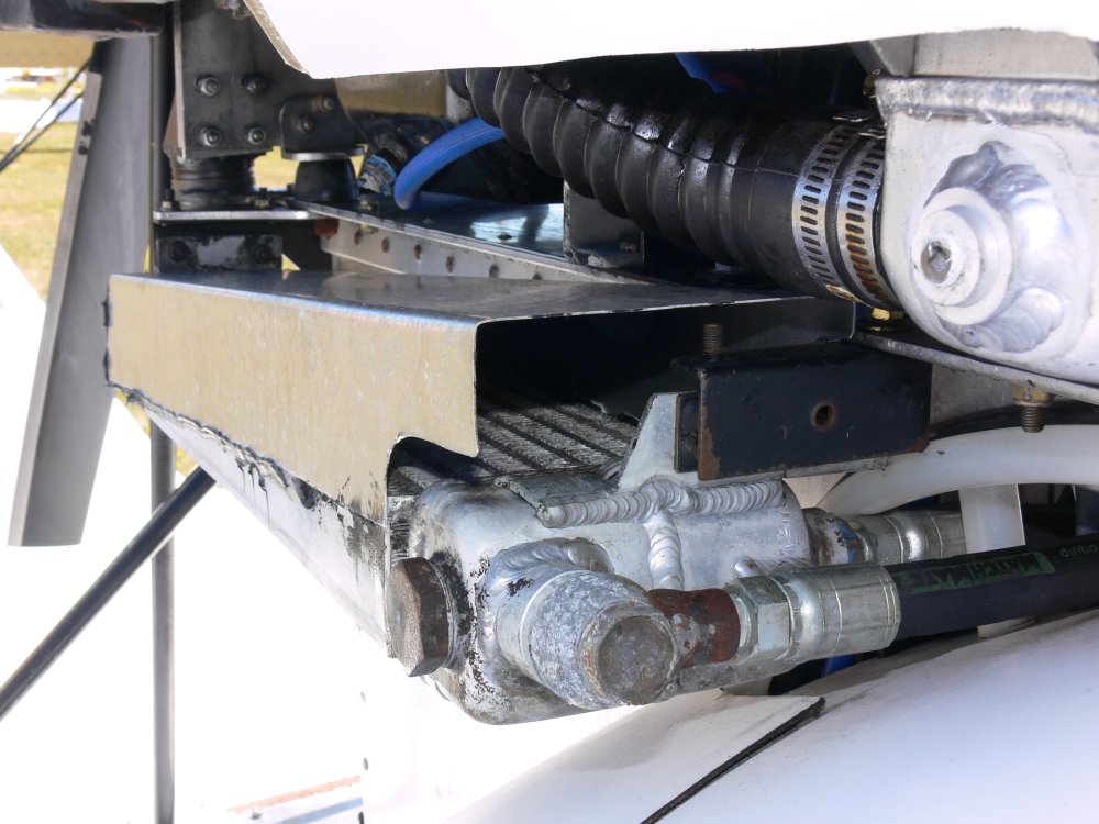
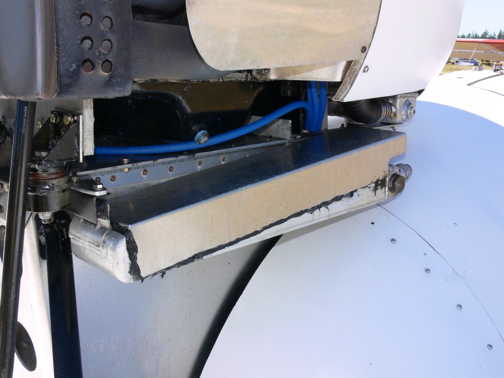
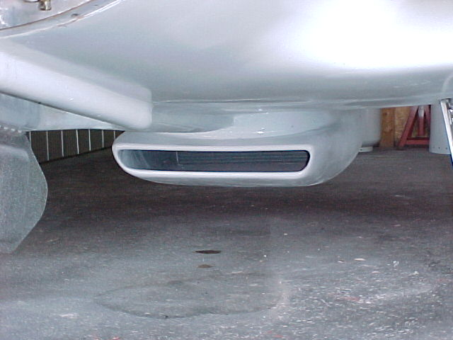
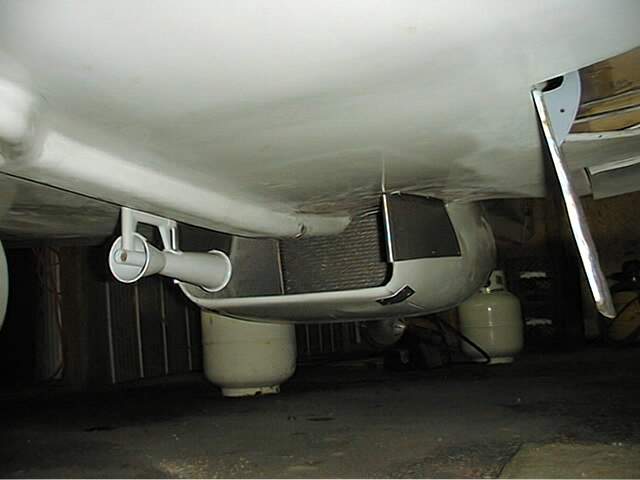
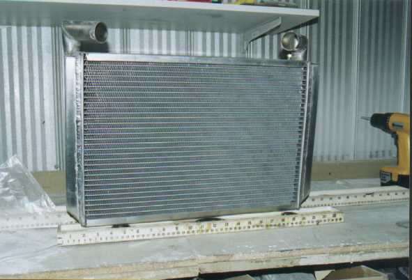
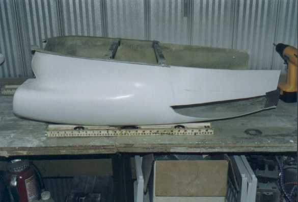
incorporated inside the pylon and under the engine. The set-up I am using in
the Merganzer is a lot like Rino's. One oval shaped inlet sub-divided into
three openings. The middle opening supplies air to the oil-cooler located in
front of the engine, and the two out- side openings supply air to the two
heat-exchangers. All three have separate ducts that are sealed appro-
priately. The two outside ducts channel air to the sides of the engine and
then down into the heat-exchangers.
From there the air is diverted aft and out of the augmentation slots. The
air exiting the oil-cooler is allowed to flow through the engine compartment
and thus removes residual heat radiating off the engine itself. Given the
space constraint's we have in our planes, there is really no other
configuration that will work with- out adding unnecessary cooling drag to an
airplane that is already burdened with excessive drag. It is, of course, a
seaplane,...with a boat-hull, spray-rails, a step, and if thats not enough,
a bi-plane that does not have the recommended cord-length vertical
separation between the wings. In short, we do not need any more drag.
I am sending some pictures that hopefully will clarify what I am saying.
P.S., Sorry for the long-winded dissertation; but, difficult problems
require it. Also, I will be sending the pictures as a separate post. Thanks.
Frank R. Clementi
The RV9 is a low drag airplane and perhaps near the minimum drag bucket
at 150 MPH. The cruise HP could be as little as 90 to 100 HP.
What was the fuel burn. Giving the Soob the benefit of the doubt the BSFC is
probably around .42. At 100 HP that would be about 6.7 GPH. If it is less than
that it is less than 100 HP.
Think of it like this. The slower the airplane the thinner the core required
with a given volume. 400 MPH P51's could get away with 11 inch thick cores. The
pressure available to force air through the core is 16 TIMES higher at 400 MPH
than it is at 100 MPH. At 200 MPH it is FOUR TIMES higher.
One can always go up on the core volume if you have the room. Properly done with
a 2 inch core about 500 to 600 cubic inches appears to be necessary. More if you
go up on the core thickness and down on the core linear dimensions.
On the other hand I have no idea how high the drag is on the Goose.
Also sea planes tend to take a long time to get up on the step and need
a lot of HP to take off. The real cooling problem is during take off and climb
out. Not cruise. Almost anything will work during cruise.
Here is what works on a Coot. This rad is about two inches thick I think. Ken
Welter uses a 3:1 gear box and sometimes NOS to get on the step.
Your welcome to try of course. Nothing bad about confirming what others have
tried. It is good for us. Last really thick rad airplane we had was a Lancair
320/360 that never got out of the pattern with a 4 or 5 inch thick rad in a P51
type scoop. The ducting appeared ideal at first. Then it was sledge hammered and
it did not help.
Paul Lamar
--
The Rotary Engine NewsLetter. Powered by Linux.
ACRE NL web site.
http://www.rotaryeng.net
Youtube key word UTUBPLEASE
Copyright 1998-2008 All world wide rights reserved.