Paul, Sandy et. al., I have a glass goose project, and due to major
modifications that I plan on making in order to address what I consider major
short-comings, I will no longer be allowed to call it as such. It is now
called a Merganzer. I'm not going to address these changes, as they have
already been posted on the Seahawk, Glass Goose builders web-site. I will,
however, join in on the current discussion on cooling this beast. This
assumes we are working with a liquid-cooled engine.
But first let me share with everyone a recent experience. Last week-end I
went with a fellow EAA member to Plymouth, Massachusetts to help him ferry
his recently purchased RV-9A back home to Zephyrhills, Florida. A really
nice airplane. It has an Eggenfellner Subaru engine (165 H.P., 4 cylinder)
in it. It ran flawlessly, in spite of what I would consider a less than ideal
cooling con- figuration. Let me explain. The heat-exchangers were too small
(Core Area: 5.5"x7.0"x3.0"=115.5 cu. in.x2 H.E.'s=231.0 cu. in.
/ 165 H.P.= 1.40 cu. in. per H.P.), the ducts leading to the heat-exchangers
face did not have a well shaped trumpet diffuser, they were not sealed to
the heat-exchangers, nor were they sealed to the cowl-openings; not what is
recommended in "How To Cool A Wankel". In spite of all this, they did an
adequate job of cooling this engine for 1,200 miles or 8 hours of run time
during 2 days of travel.
I did say "adequate job of cooling" not "great job of cooling". Let me
explain. At 4,800 RPM's (@ engine) the water temp ran about 210*F-215*F. We
were told not to exceed 230*F. So, based on this information, we were OK.
However, I don't feel comfortable with water temps over 200*F. At my
insistence, the owner reluctantly agreed to reduce the throttle to 4,500
RPM's and we then saw water temps from 197*F-200*F. This made me feel more
comfortable. Little by little the owner advanced the throttle until we saw
water temps of 200*F- 205*F @ 4,600 RPM's - 4,700 RPM's: a compromise I
guess. We left it there and saw 148 MPH-150 MPH cruise with no problems.
Now, I'll stick my neck out a little. I know that most of you believe a
thin, wide heat-exchanger will cool better than a compact, thick one. Maybe
that is so; but, in our Seahawks, Glass Goose, Merganzer airplanes, we don't
have room for a wide, thin heat-exchanger. And since I have witnessed a
poorly designed cooling system using compact, thick heat-exchangers do an
adequate job of cooling, I suggest that this is the approach to be taken
with our particular aircraft. I also did some research on heat-exchanger
core-volume requirements. I measured the radiator cores of a Toyota P/U, a
Toyota 4-Runner, a Ford F-350 P/U, and last but not least, the P-51 Mustang.
Then I compared the volume of each core (in cu. in.) to the rated H.P. of
each engine. What I found was a range of 3.4 cu.in. to 3.7 cu.in. of core
per H.P. The average was about 3.5 cu.in. per H.P. Slightly more than 3.0
cu.in. per H.P. recommended, but not by very much. Now for the argument of
thin versus thick cores. While I will not disagree that a wide, thin
heat-exchanger works better than a compact, thick one (as far as cooling
efficiency); what about cooling drag?
If you have a wide, thin core, then you are using a greater volume of air
through the heat-exchanger. More air...more cooling drag. What's your
opinion? Also, I am sure that a 2 inch deep core will have better cooling
efficiency than a 4 inch deep core, but, I am of the opinion that, while not
ideal, the rear 2 inches of a 4 inch deep core is doing some cooling. The
evidence of this is the Eggenfellner Subaru engine in the aforementioned
RV-9A. If space is a major factor (which is a fact in our planes), then why
not design a system using compact, thick heat-exchangers which can be
incorporated inside the pylon and under the engine. The set-up I am using in
the Merganzer is a lot like Rino's. One oval shaped inlet sub-divided into
three openings. The middle opening supplies air to the oil-cooler located in
front of the engine, and the two out- side openings supply air to the two
heat-exchangers. All three have separate ducts that are sealed appro-
priately. The two outside ducts channel air to the sides of the engine and
then down into the heat-exchangers.
From there the air is diverted aft and out of the augmentation slots. The
air exiting the oil-cooler is allowed to flow through the engine compartment
and thus removes residual heat radiating off the engine itself. Given the
space constraint's we have in our planes, there is really no other
configuration that will work with- out adding unnecessary cooling drag to an
airplane that is already burdened with excessive drag. It is, of course, a
seaplane,...with a boat-hull, spray-rails, a step, and if thats not enough,
a bi-plane that does not have the recommended cord-length vertical
separation between the wings. In short, we do not need any more drag.
I am sending some pictures that hopefully will clarify what I am saying.
P.S., Sorry for the long-winded dissertation; but, difficult problems
require it. Also, I will be sending the pictures as a separate post. Thanks.
Frank R. Clementi
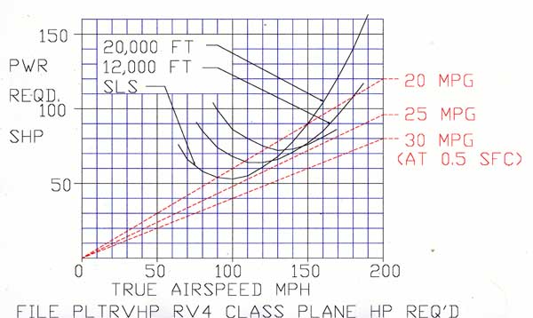
The RV9 is a low drag airplane and perhaps near the minimum drag bucket
at 150 MPH. The cruise HP could be as little as 90 to 100 HP.
What was the fuel burn. Giving the Soob the benefit of the doubt the BSFC is
probably around .42. At 100 HP that would be about 6.7 GPH. If it is less than
that it is less than 100 HP.
Think of it like this. The slower the airplane the thinner the core required
with a given volume. 400 MPH P51's could get away with 11 inch thick cores. The
pressure available to force air through the core is 16 TIMES higher at 400 MPH
than it is at 100 MPH. At 200 MPH it is FOUR TIMES higher.
One can always go up on the core volume if you have the room. Properly done with
a 2 inch core about 500 to 600 cubic inches appears to be necessary. More if you
go up on the core thickness and down on the core linear dimensions.
On the other hand I have no idea how high the drag is on the Goose.
Also sea planes tend to take a long time to get up on the step and need
a lot of HP to take off. The real cooling problem is during take off and climb
out. Not cruise. Almost anything will work during cruise.
Here is what works on a Coot. This rad is about two inches thick I think. Ken
Welter uses a 3:1 gear box and sometimes NOS to get on the step.
Your welcome to try of course. Nothing bad about confirming what others have
tried. It is good for us. Last really thick rad airplane we had was a Lancair
320/360 that never got out of the pattern with a 4 or 5 inch thick rad in a P51
type scoop. The ducting appeared ideal at first. Then it was sledge hammered and
it did not help.
-----------------------------------------------------------------------
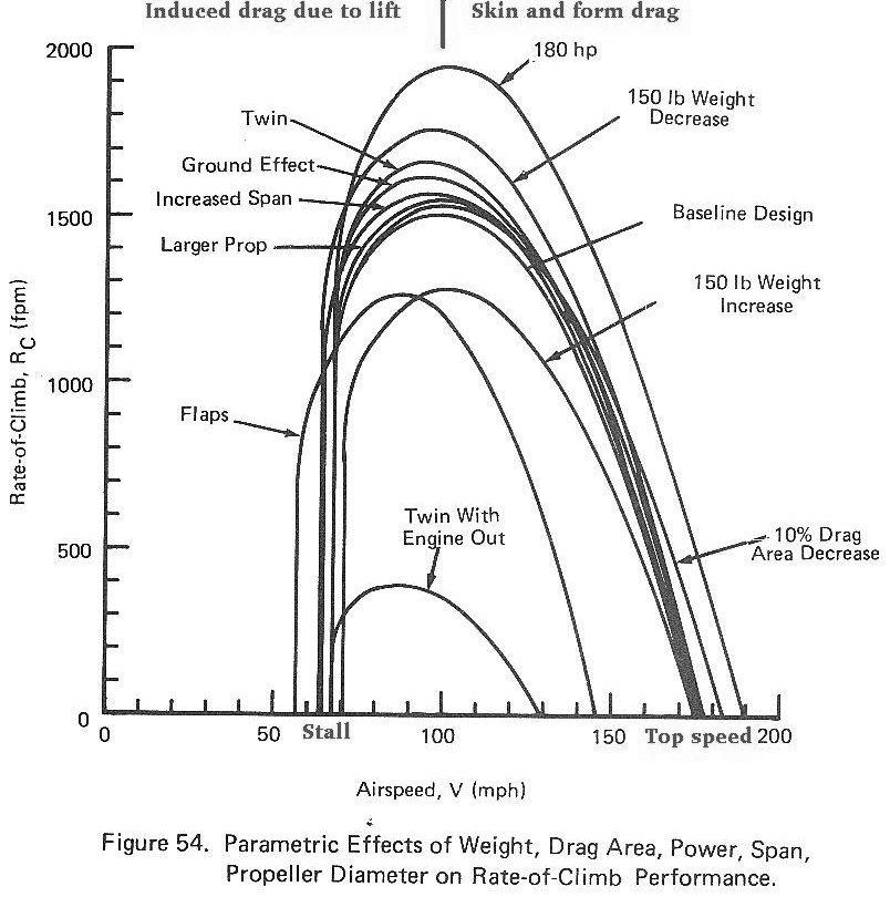
I failed to answer Frank's question about drag. Here is a rough approximation of
what the drag rise curve looks like on a flying boat or float plane.
At first there is a thing called displacement drag and that is the hull moving
through the water causing a bow wave. Full power is used up until the hull
reaches planning speed and the hull is on the step. There might be a small drop
in hull drag as the airplane accelerates toward takeoff speed. You are still at
full power. Now you can fly in ground effect low over the water, reduce the
power and give the engine a chance to cool off. There is a lot of low speed drag
due to lift which is called induced drag and it is caused by the four vortexes
coming off the wing tips. Flying close to the water reduces this drag. Once you
start climbing however a lot of HP is needed just to climb. It has nothing to do
with aerodynamic drag but simple aerodynamic drag is a small part of it. Induced
drag is high. When you raise any weight, lets say the gross weight of the
airplane is 2000 pounds, at 500 feet per minute that is 1,000,000 foot pound
minutes or 17,000 foot pounds per second. One HP is 550 foot pounds second so it
takes 30 HP to just to lift the weight. That does not including drag. That would
be the same if you were lifting the weight with a rope and pulley. From this
speed down cooling is the big problem. If you can't get this solved you are not
going to fly.
Lets say we are now at our cruising altitude and we are at the last hump. As we
pick up speed drag starts to fall off as induced drag due to lift is lowering.
Now we are in the drag bucket and it then takes a modest amount of HP to
maintain this speed. If we try to go faster drag starts rising again.
However the air pressure available to cool is rapidly rising so generally
speaking cooling is not much of a problem from this point up to near top speed.
More on cruise cooling drag shortly.
--------------------------------------------------------------------
Ok lets talk about cooling drag. Lets say we had a scoop on the front of our
airplane and it did not add to the overall frontal area. Frontal area is a
technical term meaning the total cross sectional area of the aircraft and
overall drag is proportional to this number. It could be a maximum anywhere
along the length of the airplane. It has nothing to do with the shape of the
front of the airplane.
Now if this scoop was connected to a pipe and the pipe came out of the back side
of the airplane air would flow in the front and out the back with out slowing
down. Yes there is a small amount of skin friction in the pipe but we will
ignore that for a moment. Essentially there would be no drag. Now lets say we
put a heat exchanger in the pipe. What happens? Well the air is going to slow
down ahead of the heat exchanger and increase the pressure at the scoop opening.
If you add up the area of the scoop and multiply it by the pressure you will get
the cooling drag. In fact you will see this same pressure at the face of the
heat exchanger as well. Drag is a constant times the velocity squared. Well we
can come up with some super efficient heat exchanger that transfers the required
heat with out adding drag. That is tantamount to perpetual motion as X number of
square inches of metal needs to be in contact with Y amount of air in order to
transfer the needed heat.
How do we do we improve the heat transfer. We can use more fins per inch with
more tubes per inch but that increases the drag. Since drag is a constant times
the velocity squared how can we slow the air by half and reduce the drag to 25%?
We expand the pipe to double the area still keeping it inside the fuselage or
cowling without adding to the frontal area and we can slow the air to half the
velocity coming in the scoop and reduce the heat exchanger drag to 25%. As you
can see the heat exchanger drag is the primary factor on the over all cooling drag.
Kays and London Compact Heat Exchangers fooled around for 20 years with your tax
money and they found that the larger the frontal area of the heat exchanger the
thinner it could be and still transfer the same amount of heat. The drag of the
heat exchanger was drastically reduced. Why is this true. Well the rate of heat
transfer is proportional to the temperature difference between the air and the
metal. The first part of the heat exchanger is doing the most work and as the
air passes through the heat exchanger it heats up. This hotter air does not
absorb as much heat so it is doing much less work as it flows past the last part
of the heat exchanger. In theory the most efficient heat exchanger is infinitely
thin and infinitely large. The air going through it would be very slow indeed
and therefore the drag would be a minimum.
The problem boils down to how do we slow the air and still keep the air velocity
constant over the face of the heat exchanger. That is where Kuchemann and Weber
Aerodynamics of Propulsion come in. Also Kays and London addressed this issue.
We have a scoop. What does the duct look like between the scoop and the heat
exchanger? That one of the things I discuss in my book and what we have been
talking about on here for the last ten years. I won't get into it now.
The next thing to know is what we have in a cooling system is a very inefficient
jet engine. We are taking air in, heating it up and squirting it out the back.
In effect we are offsetting the drag of the scoop and the heat exchanger. If we
suck the air out the back we add drag. That is what cowl flaps do. If we use the
otherwise wasted energy in the exhaust to suck the air out that is a positive.
The last thing is if you increase the pressure in the entrance of the scoop some
of the air is going to say: Hey I am not going in that hole and I will just go
around it reducing the heat transfer. You need X cubic feet of air at Y velocity
to cool the engine. Reducing the mass of air flowing through the heat exchanger
will reducing the cooling effect. Its a balancing act.
Paul Lamar
--
The Rotary Engine NewsLetter. Powered by Linux.
ACRE NL web site.
http://www.rotaryeng.net
Youtube key word UTUBPLEASE
Copyright 1998-2008 All world wide rights reserved.