Clint "Sandy" McNabb wrote:
Paul,
Does the wedge shaped diffuser require a trumpet shaped diffuser in
front of it, or can is it effective alone?
Sandy
Glass Goose
----------------------------------------------------------------------
It is stand alone.
BTW Here is something you might try in front of the engine.
Four cores 10" by 10" by one inch thick.
Plumbing is rather complicated however.
All four should be plumbed in parallel. Big tank on top and bottom.
It should come out to be about a one foot cube more or less.
Weld the cores to the bottom plate of the tank first.
Then weld on the top plate. The top plates will need external
stiffening ribs as 30 psi will pooch them out for sure.
I don't know where you will find a 10 inch square coolant core but oil
cooler cores might work OK for coolant. If you make it five cores one
could be the oil cooler. You might have room for six cores side by
side. Less marginal.
Paul Lamar
----------------------------------------------------------------------
-
Paul,
Thanks for the folded core idea. I'll study that one. I guess it's an
understatement to say that there seems to be a lot of physics
happening with heat exchangers, some of which seem to be contradictory
to this amateur. My first concern with the folded core is the exhaust
area which your book suggests at least 10" for optimum performance. My
next concern is that your book recommends 600 to 800 ci of water
cooling for the Renesis. I'm really having trouble fitting in all the
required water cooling (600-800 ci) and oil cooling requirements (200
ci) in the space allotted. It's like trying to put 10 pounds of "stuff" in
a 7 pound bag.
My question about wedge shaped diffusers is founded in my latest two
ideas for "up front" cooling with two heat exchangers. One design with
wedge shaped diffusers on the outside of the core requiring exhaust to
the inside of the cowling (see Intakes outside 1.jpg, Intakes outside
2.jpg, and Intakes outside exhaust.jpg attached), and the other, to
put the intake diffusers on the inside and thereby exhausting air
outside the cowling (see Intakes inside 1.jps, Intakes inside 2.jpg,
Intakes inside side view.jpg, and Intakes inside top view.jpg
attached)
I'm able to fit in a 14" x 12' x 2" core on the aircraft right and a
12.5" x 12" x 2" core on the left with either design. The left one is
shorter in order to make room for the alternator and pulley (See
Alternator deconflict.jpg attached). That's a total of 636 ci of water
cooling core.
While it is near impossible to get enough effective ducting beside the
engine down into the pylon for 600 ci plus water cooling cores, I can
easily get more than enough ducting down to 200ci oil cooling core
(probably two 100 ci cores) (see Intakes inside duct for oil cooling
area.jpg attached).
The Ducts on the inside cooling design 1 & 2(Small).jpg show a
possible cowling design for that plan. The intakes on the outside of
the core cowling would be similar.
Advantages and disadvantages of the intakes on the inside of the cores
(as I see it):
1. The exhaust may be in a high pressure area of the cowling and
thereby not get enough pressure differential.
2. I would assume since there is some frontal air exposure that
louvers would be required. I'd have to design and fab those louvers.
3. I think the louvers would make canopy design more problematic.
4. There would be plenty of exhaust area (ambient air) behind the core
if #1 doesn't adversely affect it.
Advantages and disadvantages of the intakes on the outside of the cores.
1. Easier, simpler, cleaner canopy design
2. I could use fan(s) to suck air when required (I don't recall if
there has been a discussion about using fans in airplanes)
3. Both cores would exhaust into the same common area. Although a full 10"
is not available in all areas of the exhaust for each core, it is
pretty roomy (see Intakes inside duct for oil cooling area.jpg). I
would like to put intakes and 60sq ins of ducting the that same
exhaust area for the oil
cooler(s) in the pylon (see ducts on the inside cooling design 1
(Small).jpg). If that adversely affects the exhaust area of the cores
then I'll have to have to move the oil cooler intakes elsewhere.
4. The cores' exhaust would flow over the engine. I assume that would
reduce engine heat build up.
What do you think?
Scott Gettings and I are also studying another plan to put one large,
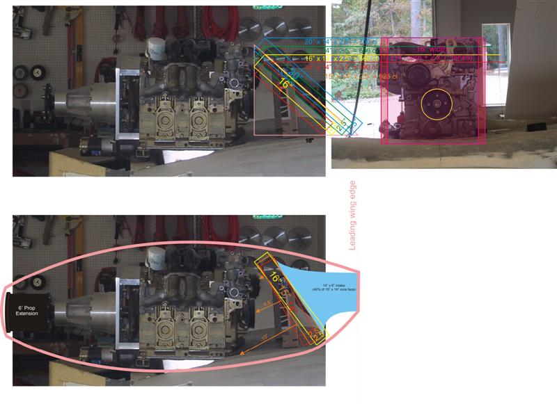
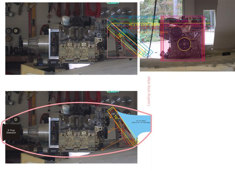
thick 15" x 14" core leaning back in front of the engine. The
difficulties I see is there will not be enough room to get 10" of air
exhaust toward the middle and at the top of the rad. And, then on the
other side of the core there doesn't seem to be enough room to locate
a proper trumpet diffuser in order to slow down the air before it
reaches the rad face. Also, the rad is going to have to be
thicker...2.5" (yields 525ci) or 3.0" (yields 630ci). Is it better to
have 525 ci with a 2.5" core or 630 ci with a 3.0" core on a 140 mph
airplane?
Wow! That's a lot of stuff. Thanks for your advice.
Sandy McNabb
Glass Goose with a Renesis
You can get away with less than 600 cubic inches if the ducting is
well done and the core is thin. People have used as little as 500 ci.
The cooling air exhaust up and out will work the best. Both scoops
close together. The wedge diffuser will insulate the core from engine
heat. Also the engine will serve to limit the flow if the cores
exhausted inwards towards the engine.
The K&W duct is too short and the back of the rad is too close to
everything.
All of these ideas are OK. Making the cowl larger will certainly help.
It adds a bit of frontal area however. I'll think about these ideas some
more.
---------------------------------------------------------------
If you don't mind adding a bit to the frontal area make the cowl wider.
Use two 49 square inch constant area ducts from the front of the cowl
back to two cores mounted on either side of the gear box.
The prop will help extracting the air. The cores are the same size as
the ones you suggest. Namely 12 by 16. The spinner shown is 12 inches
in diameter.
----------------------------------------------------------------------
----- It is kind of easy to make the cowl wider by adding a strip in
the center.
Current cowl is 28 inches wide as I recall. This one is 35 inches wide.
3.5 inches more on each side. Seven inch center strip.
The duct can be carved from styro foam and covered with duct tape to
give a smooth inside surface. The styro foam will dissolve in acetone.
----------------------------------------------------------------------
--- The more I look at the folded core idea the better I like it. A
real tight cowl is possible. Less frontal area. There is plenty of
room behind the block for air exit. In fact a small fan could be
mounted on an extension of the e-shaft t0 help cool at low speeds.
It is ideal for a P51 type scoop on other airplanes.
The cores are one inch thick 10 by 10 and five are dedicated to water
cooling and one to oil. 500 cubic inch for water. No doubt in my mind
this will work fine. Will work best with a 10 quart oil pan.
I think Jerry Hey may weld this up for you.
Paul Lamar
Paul, you are hard at work on this project again! We all appreciate your
efforts, and in fact it has got me working on the wind tunnel model again.
When you visited my project, I showed you a front-mounted, vertical,
90-degree,
L-shaped radiator option using wedge diffusers. You said this should work
if I
added an upper cowl flap to improve exit airflow during low speeds / high
AOA.
Such a radiator can provide from 500-600 c.i., depending on the height and
thickness. (I'm not on my home computer, so I can't send the pix /
drawings
till Sat.)
The 90-degree design allows the center of the (point) of the radiator to
rest at the front/center of the cowling, and the center would have about 13"
of
clearance back to the engine. The backs of the radiator on each side get
progressively close to the engine, but the average clearance looks
reasonable.
(Note this is very different than the last 2 versions Sandy submitted).
Your current drawings don't seem to take into account the limitations of the
cowl and canopy. There is only about 14" from the front of the engine to
the maximum frontal aspect of the cowl, because the canopy has to open.
This would be VERY difficult to change. So we only have about 14" total to
work with from the front of the canopy to the engine. Wouldn't this
prevent adequate exit airflow from the back of a folded radiator? Would an
upper cowl flap be applicable to this design as well?
Until recently, I was pretty much set with the front, L-shaped radiator
design.
I was mainly working on the various oil cooler options we had discussed
(turning vane, etc.). I'll send some pix this weekend (Sandy, you may have
a couple of these pix available as well).
Scott Gettings
I guess the dwgs are wrong as I have 52 inches from prop flange to front of
the cowl. Here is the offending dwg. Well that is disappointing.
Is there an official dwgs out there?
------------------------------------------------------------------------
According to this overlay the 52 inch number is about right.
That gives 8.5 inches from the e-shaft pulley to the back of the cooling
block which is just about enough.
Please double check for me.
Paul Lamar
------------------------------------------------------------------------
Paul,
Thank you very much for all your efforts on our Goose cooling issues. You've
put a lot of thought and effort into our challenges. We do appreciate it.
The measurement from the front edge e-shaft pulley to the wing's leading
edge/back of the canopy (coincidental point) is exactly 16".
I've pretty much resigned myself that I'm going to have to fab my own
cowling. The original cowling is for a low, wide Lycoming. A custom cowling
for a rotary would be taller and narrower. Plus it would give a lot of
flexibility for the cooling options.
The folded core seems very promising to me. I'll do some measuring and
thinking on it. What do you think the minimum required width and length
would be for that arrangement?
I've got to get an alternator bought and installed so I can better determine
the exact space available for cores and ducts.
In an above message you said the wedge diffuser, with the scoops on the
inside design, were too short. What are your guidelines for how far the
scoops should extend beyond the leading edge of the rad?
I'll get back with you soon.
Thanks,
Sandy McNabb
16 inches is just about right for the folded core. Around the pulley there is
more room up to the RX8 front cover.
The folded core is less than 10 inches long and about 12 to 14 inches wide.
About a little less than the frontal area of the engine itself. Given the
exhaust system and the alternator.
It was the Kuchemann & Weber duct that was too short. This dwg here.
A six inch prop extension will allow fuselage sides that don't go back
at such a sharp angle.
Paul Lamar
--
The Rotary Engine NewsLetter. Powered by Linux.
ACRE NL web site.
http://www.rotaryeng.net
Youtube key word UTUBPLEASE
Copyright 1998-2008 All world wide rights reserved.