Clint "Sandy" McNabb wrote:
Paul,
I'm really warming up to your folded core concept if you think there
is enough cooling there. I did some measuring and drawing to see how
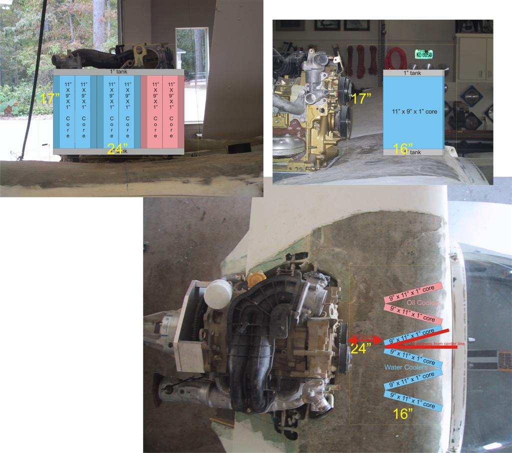
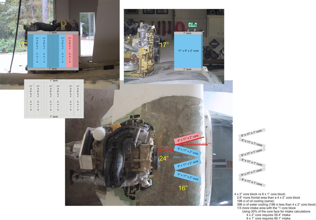
it fits (see Folded core for a Glass Goose 1.jpg attached).
Since your book says that one third of the Renesis cooling is through
the oil coolers I added one core to your plan to give the design the
1/3 to 2/3s balance...and it's also symmetrical now. I set the angle
between the cores at 30 degrees. Fifteen degrees for each core works
out to the equivalent of a 3" x 10" intake for the wedge (10" x 10"
core = 100 sq in x 30% requires a 30 sq in intake. The core is 10"
high so the width is 3".....thus 15 degree from centerline). I certainly
could be off base with this direction.
I drew yellow lines on pictures of three angles to describe what I
consider the rough maximum area in front of the engine for cores.
My only concern at this time is the intake area. Would it require a
10" by 24" intake for all those cores to get their air???
Looks like I could even make the cores taller than 10".
Thanks very much for your help with this.
Sandy McNabb
Glass Goose with Renesis
Thats great Sandy. I am pretty excited about the idea too. I don't know why
this did not occur to me a long time ago. The concept is perfect for the
Goose
Subtract the thickness of the cores from the intake area as the block itself
serves the scoop function. BTW From here on out I am going to call it a
cooling block. Lots of scoop area is not a bad thing necessarily. It depends
on what is behind it. If the core porosity is low it never builds full
dynamic pressure and therefore drag is reduced. That is fundamental to this
scheme.
Here are some pictures of a WW II Typhoon I saw in Henden that uses a
somewhat similar scheme. The core used is quite porous however it would
still benefit greatly from a folded core.
You have tanks shown on front and back of the cores. You don't need those.
Use two large tanks. One on top and one on the bottom. Slots are cut in the
plate and the cores are welded around the slots. Then a top plate is welded
on.
Thats simplifies the plumbing and reduces the depth of the cooling block as
well as the width.
A minor point. I think you should swap back to front so the outer cores
themselves can be the outer walls of the scoop. Also the engine is bit
higher than 12 inches so perhaps the cores can be 11" high by 9" wide.
That would make the block 13 inches high by about eight or nine inches deep
giving a bit more room behind the block for the air to escape.
It all depends on what you can find out there. Perhaps some aluminum heater
cores will work.
Paul Lamar
----------------------------------------------------------------------------
-------
Paul,
I'm ready to start refining your cooling block plan.
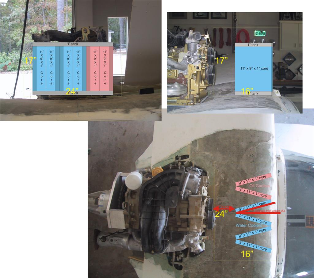
As you recommended, I turned the cores around 180 degrees, made 11" x 9"
cores, and added 1" tanks at the top and bottom rather than the ends. (see 6
- 1 inch core block mod 1 (Large).jpg attached).
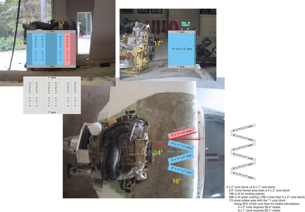
I'd like for you to take a look at a 4 x 2" core block plan (see 4 -2 inch
core block (large).jpg. It has some advantages.
4 x 2" core block versus 6 x 1" core block:
The 6 x 1" core block has 2.75" more frontal area than a 4 x 2" core
block
198 ci of oil cooling (same)
The 6 x 1" core block has 396 ci of water cooling (198 ci less than 4 x
2" core block which has 594 ci)
The 6 x 1" core block has 1/3 more intake area than a 4 x 2" core block
Using 30% of the core face for intake calculations
4 x 2" core requires 59.4" intake
6 x 1" core requires 89.1" intake
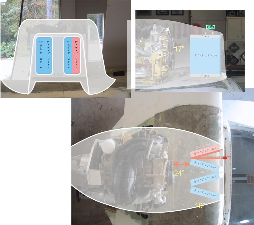
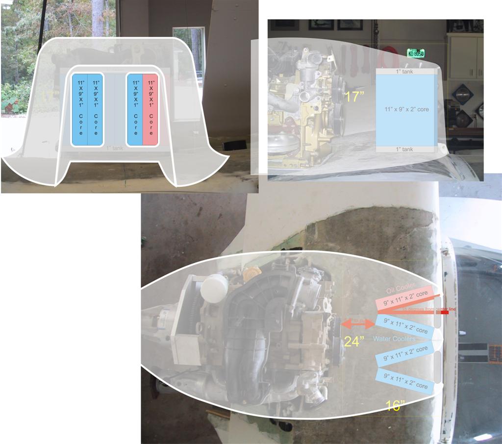
And, I've been drawing a possible cowling to house the core block (see 4 - 2
inch block cowling (Large).jpg
What percent of core face do you recommend for determining the size of the
intake in this cooling block arrangement? My drawings show 30%.
Thanks for your help,
Sandy
That is much better.
The 2 inch core defeats the idea. As K&L said in a very pithy comment :)
(I had to re-read this about 1000 times before it sank in) :)
"the resulting core shapes are characterized by large flow frontal area and
short flow lengths for the gas-flow path" The gas-flow path they are talking
about is the air flowing through the core. The thinner the better. Your cooling
drag will be less.
Paul Lamar
--
The Rotary Engine NewsLetter. Powered by Linux.
ACRE NL web site.
http://www.rotaryeng.net
Youtube key word UTUBPLEASE
Copyright 1998-2008 All world wide rights reserved.