So does anybody have a drawing or better yet 3D model of standard
rotor? If not than we'll have to wait for Paul to produce one.
Thank You Ted
Does anybody know how to calculate the radius of the rotor face?
Paul Lamar
Hey all,
Here is the excel file I have been working on. It is not finished and I
am still sorting out a couple errors here and there but it is getting
there. Eventually the thing will be all correct and allow you to change
the
variables and do all sorts of neat stuff. I just got laid off
recently from Delphi (note: F*%k the American auto industry) and have
been busy with finding a new job so I will get back on it when I get the
chance. Paul, note that the rotor equation never nets a constant radius.
This data while representative of the the points cannot be used in a
machine shop environment. This is where my questions of Solidworks 2009
came from as you would need to graph the sketch of the equation and not
a spline of a number of points. I checked with NX3 platform and SW2009
and it looks like they are too simplistic to do what pro-e does. Who has
pro-e that we can test out? I can gpo
more into it at depth but will
only do so if there are serious questions about it. Here are a couple
things that will show you whats up with what I mean. I am working
diligently to get this worked out because if my plan for a lightweight
all steel
brazed rotor works out then I can move to the next step which
is increasing the capacity of the engine and and having the weight of
the rotor as the cast iron version for the larger capacity engine be the
same as the 13b/renesis. 8500rpm to 10000 rpm limit on a 1 liter rotor.
That sound intersting to anybody?
http://www.profilesmagazine.com/p33/marsalek.html
http://esoxrepublic.com/blog/category/geometry/splines/
http://www.adras.com/SW2009-Equation-Driven-Curves.t8302-83.html
Rob Woods
If I am understanding you correctly you are saying the face of the rotor
is a
not a circular arc?
Paul Lamar
Paul,
The statement I made before is true.You can see by looking at the
graphical output on my program that the curvature in somewhat flat in
the middle where the combustion chambers are in comparison to where the
apex seals are where the equation starts to take a swooping turn which
increases the curvature. There isn't a solid radius arc anywhere in that
equation. Kenichi Yamamoto wrote the book with all the derived and
integrated formulas that net the equations of the inner housing and
rotor. If it was a simple as drawing three circles and trimming the
outside stuff I think it would have been written as such. Any attempt to
look at it so simplistically without actually taking the time to work
out what he provided us is a fools quest to put it lightly. So sagitta
has nothing to do with this. This all comes back to what I have been
speaking about. I can set up 1080 points or many times that number and
import that into solidworks and run a spline through it all. A curvature
comb placed on it will show all sorts of weirdness going on. Getting an
accurate cad profile is priority for this since any custom housings or
rotors need to be spot on for any number or reasons. There are a couple
programs that can do this and with some resourcing I can get the
profiles into Solidworks.This board is one of the resources I have and
hope that someone can work something out with this. Or someone who is
much better/smarter than I in programming Macros I can install into
Solidworks. I have one so far but havent verified the accuracy yet.
One thing that I think might be a constant arc is the side seals. They
are not an offset of the rotor profile which makes me wonder why for one
and also because how they might manufacture them. Constant section large
diameter that gets cut into three pieces maybe? Is that the reason for
not being a offset of the rotor surface?
Rob Woods
You are absolutely right. My mistake.
I have no doubt what you say is true. I happen to know however the rotors
have been machined three at a time on a turn table. I have a picture around
here someplace of the machine. I think it was a Curtiss Wright machine. This is
what fooled me.
Obviously Mazda is not doing it this way unless there is something hiding
behind the turn table. I did not see the machine used when I was in the factory
but Mazda would not let me take pictures of that part of the plant anyway.
It is
not an NC machine as the plant was built in 1969.
I laid a rotor on a piece of paper and traced the face curve.
An arc with a 9.15 radius comes pretty close. Here is a scan of the paper.
My 715 mm (28 inches) radius number was way wrong. I am not sure why. The arc
radius is more like 9.15 inches. This is something everybody can try.
This also proves your contention.
Here is the fly in the ointment. All these engines require a depression
in the face of the rotor to form the combustion chamber. What only matters is
the exact path of the apex seals. I contend a pure triangular rotor with
straight sides would work. The compression ratio would be too low but the
engine
would run. I contend an arc of some radius with a combustion chamber depression
would be close enough.
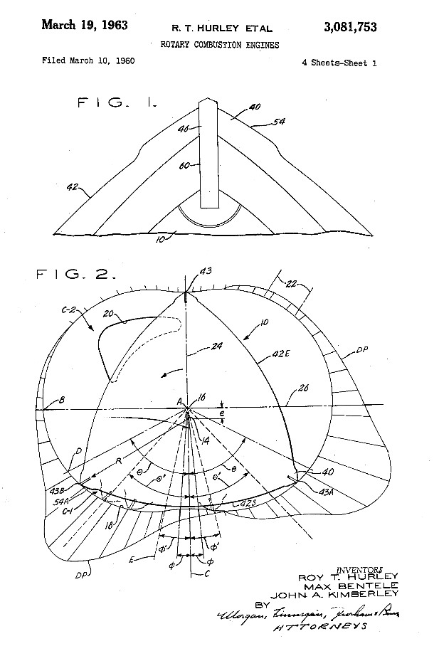
Interestedly enough here is a patent on a CW rotor face that did not come close
to an arc.
BTW Ansdale published the math in his book "The Wankel RC Engine" in
1969.
Paul Lamar
Paul,
Looking at that patent he is showing a knife edge apex seal that will
never work. Interesting shape but I would always stick to the math. All
of the work in Kenichi book is all dependent on each other as far as
calcs go so I would mess with anything. One thing to note on my
spreadsheet is that I will eventually replace the constants(all of the
2/3, 9/2 and such)in the equations with variables so we can visualize
lobe and housing number bigger that two and 3. It is a work in progress
and it is important to understand everything in and out before solid
design decisions are made.
Rob Woods
Thanks for doing all this work Rob. I am sure it will be useful when it comes
time to machine some rotors.
I see what you are saying but I think the guy drawing the patent just got lazy
and did not draw an arc on the apex seal. The apex seal had nothing to do with
the patent anyway. If you want the complete patent I have it in a pdf.
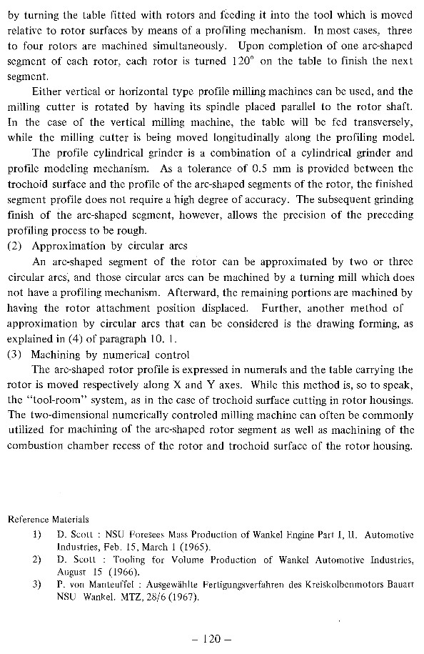
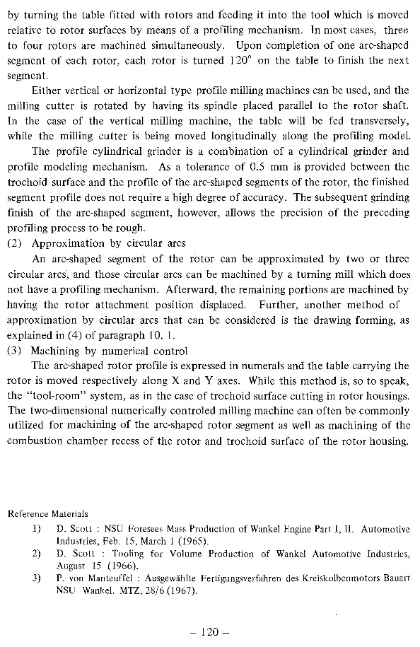
I found that dwg on how to machine rotors faces in the 1969 Kenichi Yamamoto
book on page 119 and pagwe 120. Here they are.
There is one other thing going on and that is crevasses that store unburned
hydrocarbons are not good. The side seals should be out as far as possible. I
think the side seal slot is an arc on the current rotors so an arc along side
an arc would work best. What Mazda is doing now is filling that gap with Teflon
which must be pretty expensive.
I am still thinking about how to best machine this thing out of one piece and
get some cooling fins inside for oil cooling. Steve Brazil's two piece idea
welding them together is the best idea so far. The face of the rotor must be
supported by ribs the same as the bearing support. Rotor faces have been known
to collapse. It behooves us to use the stock phasing gear and all the stock side
seals if possible. I am open to suggestions. The Curtiss Wright method is a bit
heavy. Perhaps we should not go for the lightest configuration at first but
develop the optimum aluminnum rotor one step at a time.
Paul Lamar
--
The Rotary Engine NewsLetter. Powered by Linux.
ACRE NL web site.
http://www.rotaryeng.net
Youtube key word UTUBPLEASE
Copyright 1998-2008 All world wide rights reserved.