Wow! Great Jarrett. Shows the rad is working as a turning vane.
The negative
pressure can be enhanced with an increase in rad angle. Thanks a
bunch. This is
encouraging indeed. This may actually improve the flow into the
prop.
If you get time please try it with out the rad. I also think a
one inchthick rad of larger dimensions will work great.
Paul Lamar
More to digest... the pic names call out there perameters..
I think we're getting some 'wall effect' w/ this model but...
it's a start
anyway.
Btw, on the lower speed ones w/ no rad.. the bottom left corner is
developing
into a vortex.. it has ~1/3 of a turn in the model.. some place
between
that
60mph and the 120 is the sweet spot.. at 120 it's totally
turbulant back
against
the body after the max camber point..
HTH
Jarrett
Classic separation. Just as I thought. The Goose fuselage is way
too stubby.
No wonder they have all those problems with the pusher prop. The
pusher
prop is
operating in a nightmare aerodynamic environment.
The rads will kill two birds with one stone. Turning vanes and
cooling.
Yes I did notice the wall effect. It could be moved out a bit.
the last thing to try is a one inch thick rad instead of the
current 2
inches thick.
Thanks for doing this Jarrett. Half a dozen Goose builder should
also thank
you.
Final adjustments in the real world can be made by moving the rad
in and out
and changing the angle. Scott Getting's full scale pickup truck
wind tunnel
will
tell the final tale.
Paul Lamar
It has occurred to me that one major modification that should
help greatly
is a
longer and bigger canopy. Extend it right out to the nose of the
aircraft.
That
will smooth the flow along the sides of the fuse. The boundary
layer may get
thicker but that is the lessor of the two evils.
-------------------------------------------------------
On further thought move the existing canopy 18 inches further forward
and make up the back part with fiberglass or carbon fiber for
stiffness.
Move
the hinges forward at the same time and notch the top of the
fiber glass
part to
accommodate the hinges and a longer cowl. This will lengthen the
engine
cowl and
give more room in the cowl for rads or ducts.
Then put flat side windows in the fiberglass back part to restore
side
viability.
This would be cheaper and better than a whole new plexi canopy.
Paul Lamar
--
Note that all the completed pix show VGs all over the side of the
pylon.
The manual says do not fly without these devices.
The additional space for radiators would definitely help. One
might could
move the canopy forward a few inches, but 18" would require a new
canopy
altogether. The seating, CG, instruments (which come up with the
canopy
opening), and structure are some significant issues that would all
complicate moving the canopy forward.
I'm trying hard to get some good data on the pylon airflow.
Scott Gettings
Thanks Scott.
Please take some pictures of your pitot tube positions on the mock
up.
Static pressure taps are nice but velocity rakes give a direct
read out
of air velocity. Air velocity through the rad is the bottom line.
Also short strips of cloth taped to the sides of the mock up
with a small digital camera taking movies of them would
also help. Turn the camera on jump in the truck and take off :)
The rads, located where advocated, might reduce the need for
some of the VGs. Turning vanes accomplish the same ends as
VGs. They attach the flow that becomes separated.
Paul Lamar
--
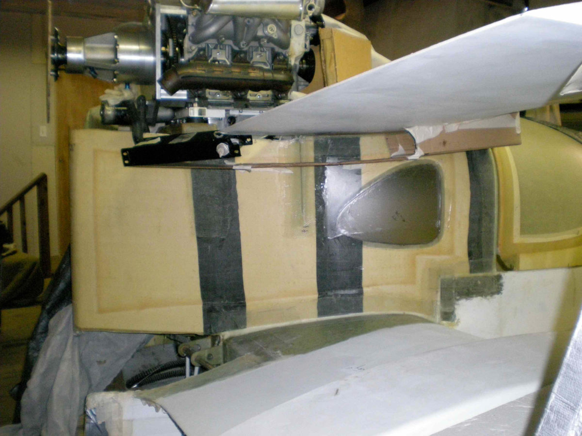
You can see the holes for the intended locations of the pressure
ports on the sides of the pylon. (Yes that is Bondo, but you said it
should be smooth and it ain't flying!). I'm also planning to have
pressure measurements on the front and back sides of any turning
vanes and/or radiators.
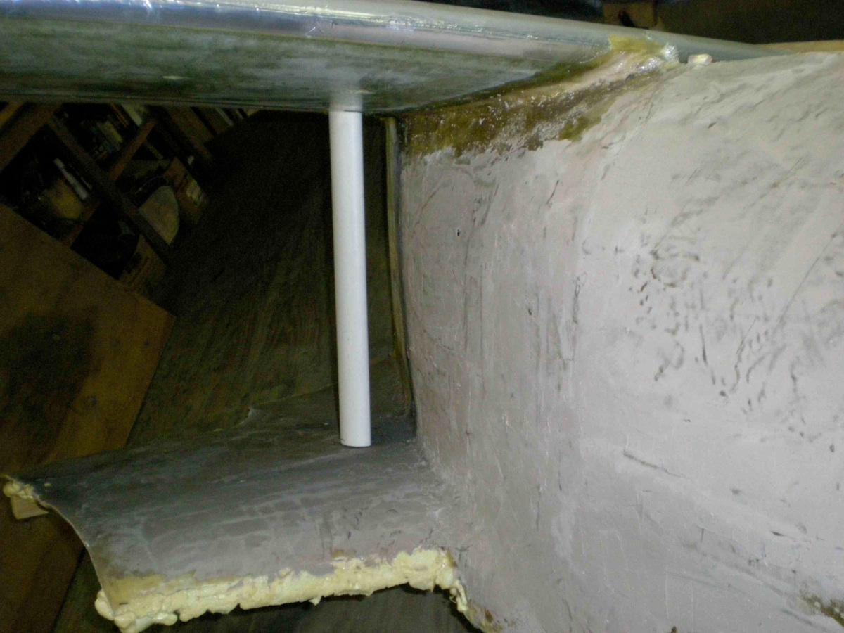
I also included pix of a known GG vane installation that worked. I
also built an X-plane model but had a hard time with some of the
pylon and tail interface areas.
Scott Gettings
We need velocity rakes in three places. One would do and move it
from place to place on three separate runs. I drew them on some 3D's.
Paul Lamar
Paul,
It looks like you are making some interesting progress with Sandy and
the front radiator "folded core" concept! The model I have been
working on mainly addresses the oil coolers. This design could be
obsolete if the folded core concept allows the oil cooler to be
placed up front in the cowling.
In any case, I have continued some work on the aerodynamic model and
am still planning on getting a bunch of data. I already have 8
static ports on the side of the mockup fuselage and pylon, and have
built 3 velocity rakes as per your suggestion. I'm not sure exactly
where to put them, however. The pylon's widest point is 3" ahead of
the leading edge of the upper wing. It then drops off at an
increasing angle for about 12", after which it recedes at a constant,
30 degree angle for about 36" back to the tip of the pylon. The
wings have a chord of about 32" at the root, and the lower wing's
leading edge is about 5" behind the upper.
I plan on obtaining data at 70 mph from 8 static ports plus 3
velocity rakes with 5 ports each, with the various configurations:
1. The basic pylon (bare).
2. Add the standard VGs.
3. Add a simple turning vane, in several locations (any suggestions
for the locations, AOI relative to the pylon wall?) See the
attached .jpg for one that is known to work.
4. Add an airfoil turning vane, in several locations and AOIs
(suggestions?)
5. Add a turning vane that includes a cooler core, in several
locations and AOIs. I'll have a pressure port on the front and back
sides of the cooler.
6. Add an under-wing armpit scoop and duct that ends in a wedge
diffuser/cooler in the wing root/cowling junction. Measurements as
above.
7. Are there other configurations that should be tested while I'm at
it? I'd like to do these all at once if possible.
Obviously, the turning vanes / oil coolers could be tested in a
number of locations and angles. I plan on testing at least 3
locations and 3 AOIs. One consideration for the center rake is in
relation to any turning vane/oil cooler. Should this rake be placed
behind the vane?
Thanks,
Scott Gettings
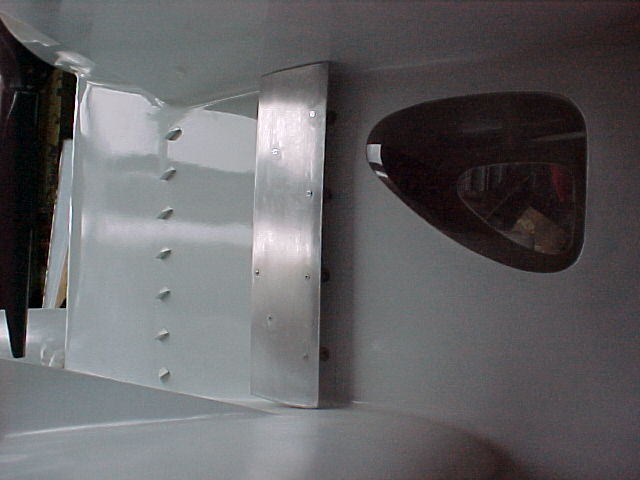
I think the side mounted radiators doing double duty as turning vanes
still has merit for the Goose. Probably a lot cheaper than folded cores.
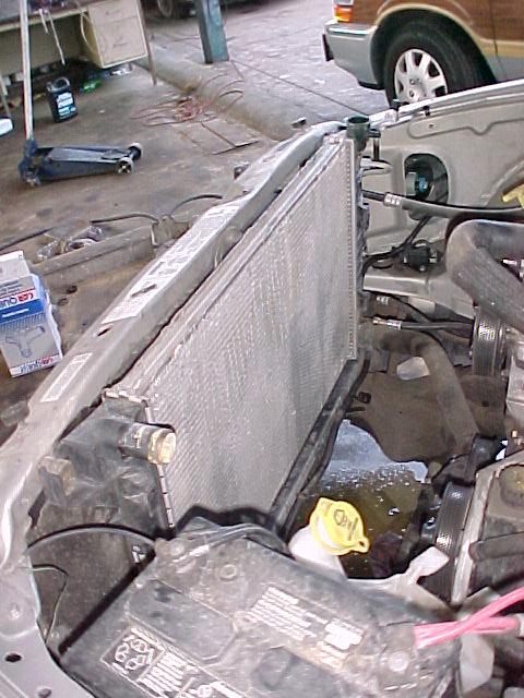
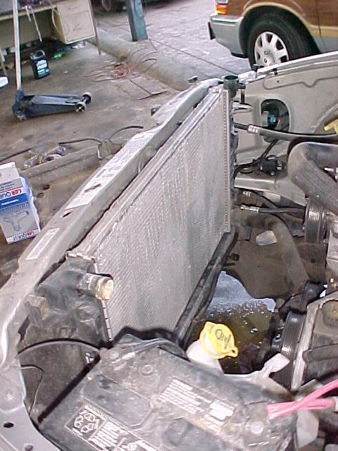
Perhaps not quite as aesthetic. I would like to see you try a large thin core
from a late model Dodge pick up truck in place of one of the turning vanes.
Does not have to work. Can be out of a wreck. If it has a large hole in it that
can be patched with a bit of foam. Saw it up to fit. An RX8 rad is similar and
will also work. There may be others. Cruise through a late model junk yard :)
The data will apply to oil coolers as well.
If you can delay till the early part of December I can show up and help. I'll
pay for the junk rad.
Paul Lamar
--
The Rotary Engine NewsLetter. Powered by Linux.
ACRE NL web site.
http://www.rotaryeng.net
Youtube key word UTUBPLEASE
Copyright 1998-2008 All world wide rights reserved.