Paul,
I'm really warming up to your folded core concept if you think there
is enough cooling there. I did some measuring and drawing to see how
it fits (see Folded core for a Glass Goose 1.jpg attached).
Since your book says that one third of the Renesis cooling is through
the oil coolers I added one core to your plan to give the design the
1/3 to 2/3s balance...and it's also symmetrical now. I set the angle
between the cores at 30 degrees. Fifteen degrees for each core works
out to the equivalent of a 3" x 10" intake for the wedge (10" x 10"
core = 100 sq in x 30% requires a 30 sq in intake. The core is 10"
high so the width is 3".....thus 15 degree from centerline). I
certainly
could be off base with this direction.
I drew yellow lines on pictures of three angles to describe what I
consider the rough maximum area in front of the engine for cores.
My only concern at this time is the intake area. Would it require a
10" by 24" intake for all those cores to get their air???
Looks like I could even make the cores taller than 10".
Thanks very much for your help with this.
Sandy McNabb
Glass Goose with Renesis
Thats great Sandy. I am pretty excited about the idea too. I don't know why
this did not occur to me a long time ago. The concept is perfect for the
Goose
Subtract the thickness of the cores from the intake area as the block itself
serves the scoop function. BTW From here on out I am going to call it a
cooling block. Lots of scoop area is not a bad thing necessarily. It depends
on what is behind it. If the core porosity is low it never builds full
dynamic pressure and therefore drag is reduced. That is fundamental to this
scheme.
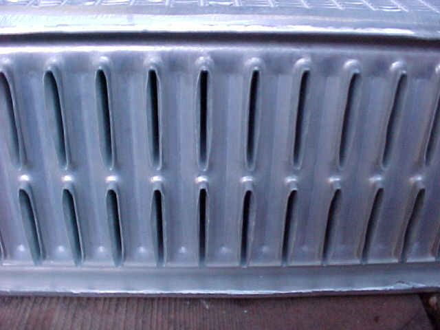
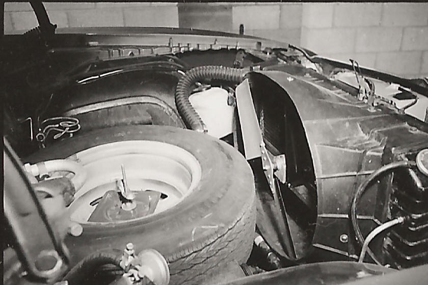
Here are some pictures of a WW II Typhoon I saw in Henden that uses a
somewhat similar scheme. The core used is quite porous however it would
still benefit greatly from a folded core.
You have tanks shown on front and back of the cores. You don't need those.
Use two large tanks. One on top and one on the bottom. Slots are cut in the
plate and the cores are welded around the slots. Then a top plate is welded
on.
Thats simplifies the plumbing and reduces the depth of the cooling block as
well as the width.
A minor point. I think you should swap back to front so the outer cores
themselves can be the outer walls of the scoop. Also the engine is bit
higher than 12 inches so perhaps the cores can be 11" high by 9" wide.
That would make the block 13 inches high by about eight or nine inches deep
giving a bit more room behind the block for the air to escape.
It all depends on what you can find out there. Perhaps some aluminum heater
cores will work.
Paul Lamar
----------------------------------------------------------------------------
-------
Paul,
I'm ready to start refining your cooling block plan.
As you recommended, I turned the cores around 180 degrees, made 11" x 9"
cores, and added 1" tanks at the top and bottom rather than the ends. (see 6
- 1 inch core block mod 1 (Large).jpg attached).
I'd like for you to take a look at a 4 x 2" core block plan (see 4 -2 inch
core block (large).jpg. It has some advantages.
4 x 2" core block versus 6 x 1" core block:
The 6 x 1" core block has 2.75" more frontal area than a 4 x 2" core
block
198 ci of oil cooling (same)
The 6 x 1" core block has 396 ci of water cooling (198 ci less than 4
x 2" core block which has 594 ci)
The 6 x 1" core block has 1/3 more intake area than a 4 x 2" core
block
Using 30% of the core face for intake calculations
4 x 2" core requires 59.4" intake
6 x 1" core requires 89.1" intake
And, I've been drawing a possible cowling to house the core block (see 4 - 2
inch block cowling (Large).jpg
What percent of core face do you recommend for determining the size of the
intake in this cooling block arrangement? My drawings show 30%.
Thanks for your help,
Sandy
-----------------------------------------------------------
Paul,
I don't know where I got those intake numbers above.
I think the correct ones are:
For the 6 x 1" cores: 11" x 9" = 99 x 6 = 594 x 30% = 178.2 sq in
For the 4 x 2" cores: 11" x 9" = 99 x 4 = 396 x 30% = 118.8 sq in for the
four core design.
One question I have about the folded core design is why isn't the exit air
impeded by the adjacent core -- which is clearly closer than the 10"
desired!
Sandy
Good question. First it is 4 inches and not 10 inches required clearance.
The rule of thumb is 40% of the core dimension hence 4 inches. See the
chart.
The core was one piece 20 by 20 it would be eight inches away.
My guess it is porous and the pressures tend to average out so the net flow
is front to back. Probably not the best but it will fit where a thin one
piece core of the same 400 square inches frontal area will not. Which is why
we are doing this :)
The frontal area of the four 10" by 10" cores in this case is the same 400
square inches.
The area expansion 400/118 or 3.3
so the airspeed through the core is one third of the airspeed going in the
scoop. Drag of the core is a about 1/10 of what it would be if not folded
and sticking straight up perpendicular to the air stream.
Drag is speed squared of course.
Paul Lamar
------------------------------------------
Paul,
I'd like to get this plan mocked up with some cardboard and wood so you can
take a look at it in relation to the engine and airframe.
Q1. How much intake to I need for each core for this cooling block
arrangement....25%, 30%, 35%, 40% of the square inches of the core face?
Q2. I'd like to move the cooling block as close to the engine as possible,
and still maintain efficiency. You said it needs 4" inches. Considering the
irregular front of the engine, would you recommend how close to the main
shaft pulley I can put the back of the core?
Q3. Do you see a need or possibility for a fan on this cooling block for
taxi, takeoff, climb.
Q4. With all things considered in the two emails above, do you like the four
2" core design or six 1" core design.
Q5. Considering the location of the water pump, how would your facilitate
the plumbing?
Thanks, Sandy
For your speed range I would choose 35% opening. I would keep the cooling
block as far forward as possible to keep the back side as open as possible.
A small fan mounted on an extension of the e-shaft would be great.
I like the six core 1 inch thick the best. The question is where are we
going to find 1 inch cores 10 or 11 inches high with header tanks? ( we only
use the lower half of the header tanks.) If you can find someone else to
agree on this design you might find cores at a wholesale discount.
The plumbing for an RX8 should be very easy. I think 1 3/8 ID silicone hose
is available so a 1-3/8 OD 90 degree tubing bends coming out of the top of
the RX8 water pump is all you need. You can eliminate that big thermostat
housing to save weight and stuff behind the cooling block. The lower one,
into the water pump, can be 1-1/2 OD for silicone hose.
Paul Lamar
----------------------------------------------------------------------------
-------
Paul,
Thanks a lot for your help on Glass Goose cooling. I'm going to do a mock up
for the 6 x 1" core you recommend, however, I have to ask the question just
for my own piece of mind.....Why do you like the 6 x 1" cooling block over
the 4 x 2" cooling block?
Considering that the 6 x 1" cooling block will:
1. Require 70 sq ins more intake area.
6 x 1": 100 sq in face x 35% = 35 sq ins of intake x 6 cores = 210
sq ins. (an intake that is 19" x 11")
4 x 2": 100 sq in face x 35% = 35 sq ins of intake x 4 cores = 140
sq ins. (an intake that is 12.7" x 11")
2. Require 4.3" more frontal area
6 x 1": 19" + 6" (1" for each core) = 25" wide
4 x 2": 12.7" + 8" (2" for each core) = 20.7" wide
3. Have 198 ci less cooling core
6 x 1": 396 ci
4 x 2": 594 ci
4. Be less cooling drag. Don't know how much.
5. Be more involved in fabricating.
Obviously, my goal is to efficiently cool the engine in all phases and go as
fast as the airplane design will allow. If you say the one inch cores are
the way...then I'm going for it!
I'm expecting to have this design custom built. Please recommend someone who
can do it.
Do you prefer silicone hoses over braided steel hoses AN hardware if cost
isn't an issue?
Thanks much,
Sandy McNabb
-------------------------------------------------------
It is very simple. The first half of the cooling block does 3/4 of the heat
transfer because the air temp increase as it passes through the core. The
rate of heat transfer is directly proportinal to the temperature difference
between air and metal. The last half does only 1/4 of the work. Therefore
thinner cores are more efficient. All other thinks being equal they have
half the cooling drag of a 2 inch core.
Jerry Hey can weld it up. You are going to research the internet and find
out where you can buy radiator cores or car heater cores. I'll help if I can
get a chance. You might make friends with a local car cooling shop owner and
find out where he buys his cores.
Paul Lamar
----------------------------------------------------
Paul,
OK....1" cores will do better for me than 2" cores at my airspeed. I'll mock
up a design with 6 x 1" cores (two of which will be for oil cooling)
Got contact info for Jerry Hey?
As you suggested I have been doing some internet research. Are there any
possibilities for this cooler:
http://store.summitracing.com/partdetail.asp?autofilter=1&part=BMM%2D70298&N
=700+0&autoview=sku I can't tell much about the size of the core. It says
4" thick but I assume that includes the fan. The intakes are smaller that
desired but maybe suitable with a manifold delivery.
Thoughts on these questions:
Do you prefer silicone hoses over braided steel hoses AN hardware?
What do you mean, "We only use the lower half of the header tanks." I assume
there is a 1" tank the completely covers the cores on the top and bottom.
A fan on the e-shaft is interesting. What affect would spinning it at 7,000
rpm be?
Thanks, Sandy
Jerry Hey
<jerry@jerryhey.com>
Yes on the silicone hoses. AN hose in that size is too costly, heavy and stiff.
The stiff and heavy part tend to crack what ever it is attached to.
In a car radiator plastic is used for the header tank and it is fastened to the
core with bent over aluminum tabs. These are unbent using a pair of pliers
and what is left is the bottom of the header tank aluminum brazed to the tubes
in the core. You weld that part to the new larger header bottom plate with large
slots in it. Then you weld on the new top plate.
That Summit racing core is not the right kind for the water part. Two of those
would be OK for the oil cooler part. This would be a better one.
http://store.summitracing.com/partdetail.asp?autofilter=1&part=BMM%2D70272&N=700+115&autoview=sku
A radiator repair shop is a good place to start for the water cores. They are
supplied by a whole sale radiator core supplier. These are the companies you are
looking for. Sometimes you have to set up a phony company to do biz with them
because you are buying several and you need a discount. If you can find somebody
else building a Goose that would help to increase the volume and reduce the price.
U S Auto Radiator Supply Co
4358 N Dixie Hwy
Fort Lauderdale, FL , 33334-3832
Phone: 954-561-2665
FAX: 954-651-5946
Jerry Hey might be talked into doing that as he already has a biz. He can tell
them he builds custom rads. Jerry lives near Fort Wayne Indiana.
ASAP Radiator & Supply
1936 N Loop Ave
Casper, WY , 82601-9227
Phone: 307-266-5606
FAX: 307-266-5604
Toll Free Phone: 800-675-5606
Business Activity: Manufacturer
For more put in "wholesale radiator supply" in google.
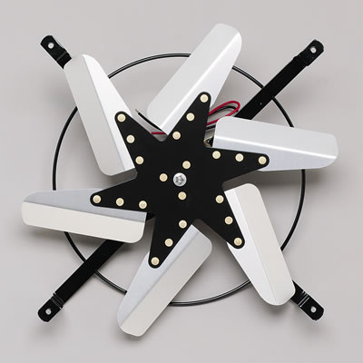
A fan on the e-shaft will be limited in diameter and blade width
so 7000 RPM should be no problem for a eight or ten inch diameter fan.
Best made from carbon fiber as the tensile strength to weight ratio
is very good. If you make the blades flexible they will lose pitch
and reduce HP consumption at high RPM like this fan I used on my mid engine
Firebird. Or get one of these Summit electric fans and cut the ends of the
blades off to 8 or 10 inches in diameter and throw away the electric motor :)
Paul Lamar
--
The Rotary Engine NewsLetter. Powered by Linux.
ACRE NL web site.
http://www.rotaryeng.net
Youtube key word UTUBPLEASE
Copyright 1998-2008 All world wide rights reserved.


