> The restrictor is on the water outlet, and the top hose is
the same size
> as a street Mazda. The radiator is a Griffin double pass
aluminum. 3" by
> 19" by 31" Two rows of 1 1/4" tubes. Both inlet and outlet on the
> passenger side.
> > Here is a picture of a cooling system that has worked for
me since 1980.
> I added the Rol-air-trol. A home made version of a air/water
separator.
> I used to manufacture heat transfer packages that used a
giant version.
> I thought Bell and Gosset made those but now I don't see one
in their
> catalogue. When pumping hot water around a building, you must
remove all
> of the air from the loop. When air goes through a pump, it
expands
> violently (cavitates) at the pump inlet and may damage the
pump, and it
> makes an awful noise at the pump, and going through fin tube
cabinets in
> each room. Nothing is as funny to school kids as a fin tube
cabinet that
> sounds like it is having a diarrhea attack. So air in the
loop is just
> not allowed. The air removing device helped me get the air
out quickly
> without hurting the engine, as my system may be drained
often. It is
> difficult to remove air from the rotary when it is level.
More so if it
> is not level. The rest of the system is what you would have
found on
> every RX-2 and RX-3. The pressure bottle is kept 1/3 full of
coolant.
> When air is delivered to the pressure bottle, it pops to the
top and
> only airless coolant can be forced back into the system when a
> temperature/volume change occurs. In two or three heat cycles
the system
> will be solid coolant. The bottle must be refilled after each
heat
> cycle, but not over 1/3 full. I have a Shrader valve on my
bottle, so I
> can be at relief pressure before the engine starts. Probably not
> required for airplanes. You could also add the pressure gage
on or close
> to the bottle for easy reading, and or, a gage on the dash to
view
> coolant pressure. The racing organizations require that catch
tank, but
> there is never anything in it.
> > I used a stock RX-2 pressure bottle, but a better choice
would be an
> aluminum aftermarket bottle to get a good selection of cap
pressures.
> The pressure cap is on the bottle. Not on the swirl pot. That
cap is
> solid and used to fill the system.
> > Lynn E. Hanover
> >
Hi Lynn,
I have a couple of questions about this cooling system. I bought an
aluminum filler neck then found out the propane bottle is steel. Do
you use a brass filler neck and solder it? Would it make any great
amount of difference if outlet came out the side at the bottom?
If the
top of the air/water separator is only 1 or 2 inches above the
radiator, is that enough?
I think I will get an all aluminum one made up. I've found a place
here that does great work welding aluminum. Since I don't have any
"track rules" I will forget about the overflow can. I tried to
buy a
simple cap for the separator and the clerks at a speed shop and an
Autozone thought I was nuts. I'm pretty sure I used to have a
car that
had a setup like that though with a separate pressure cap
elsewhere in
the system. I finally bought a regular pressure cap and
stripped the
lower seal, spring, etc. out of it.
Thanks,
Bob W.
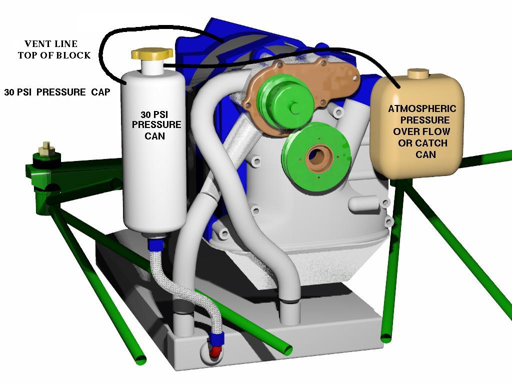
The troubles with this diagram are several.
Re-stricters are a bad idea as they reduce water flow and increase the
HP load on the pump. If you want higher pressure in the block use a 30
psi pressure cap instead.
Also the RX2/RX3 pressure bottle should be full all of the time
and some fluid should always be in the so called "fire extinguisher"
which is really an atmospheric pressure over flow bottle. When the
engine heats up and the coolant expands, tiny bubbles are formed. These
bubbles will be vented by the pressure cap to the overflow can. When
the engine cools off pure fluid will be drawn back into the pressure
bottle and the engine.
The last three diagrams are the proper way to do this type of system.
http://www.stant.com/brochure.cfm?brochure=204&location_id=179
The radiator pressure cap has a fivefold job:
1. Filler cap to access the cooling sytem,
2. Closure cap to keep coolant in the radiator,
3. Pressure cap to prevent overheating by pressurizing the system to
raise the boiling temperature of coolant and allow the automobile's
engine to operate at more efficient higher temperatures,
4. Pressure relief valve to safely and harmlessly vent excess
pressure into the overflow jug, and
5. Vacuum relief/siphon valve to draw coolant from the overflow jug
back into the radiator to prevent air from entering the system and
allowing the coolant to perform its function more efficiently.
Paul Lamar
Hi Paul,
I'm not using the restrictor. The way you've described it is the way
I had my cooling system set up in the airplane installation. I didn't
get the "the last three diagrams".
Thanks,
Bob W.
That because I screwed up and did not attach them :)
Hopefully here they are.
Paul Lamar
What's the purpose of the hose from the bottom of the 'pressure can' to
the rad?
Thanks,
--Kenny A.
http://websites.expercraft.com/kennya/
That is to let any air bubbles coming out of the rad rise to the can.
Also when you fill up the system the coolant has to rapidly get into the rad,
water pump and block. The vent lines are too small for that.
Paul Lamar
--
The Rotary Engine NewsLetter. Powered by Linux.
ACRE NL web site.
http://www.rotaryeng.net
Youtube key word UTUBPLEASE
Copyright 1998-2008 All world wide rights reserved.