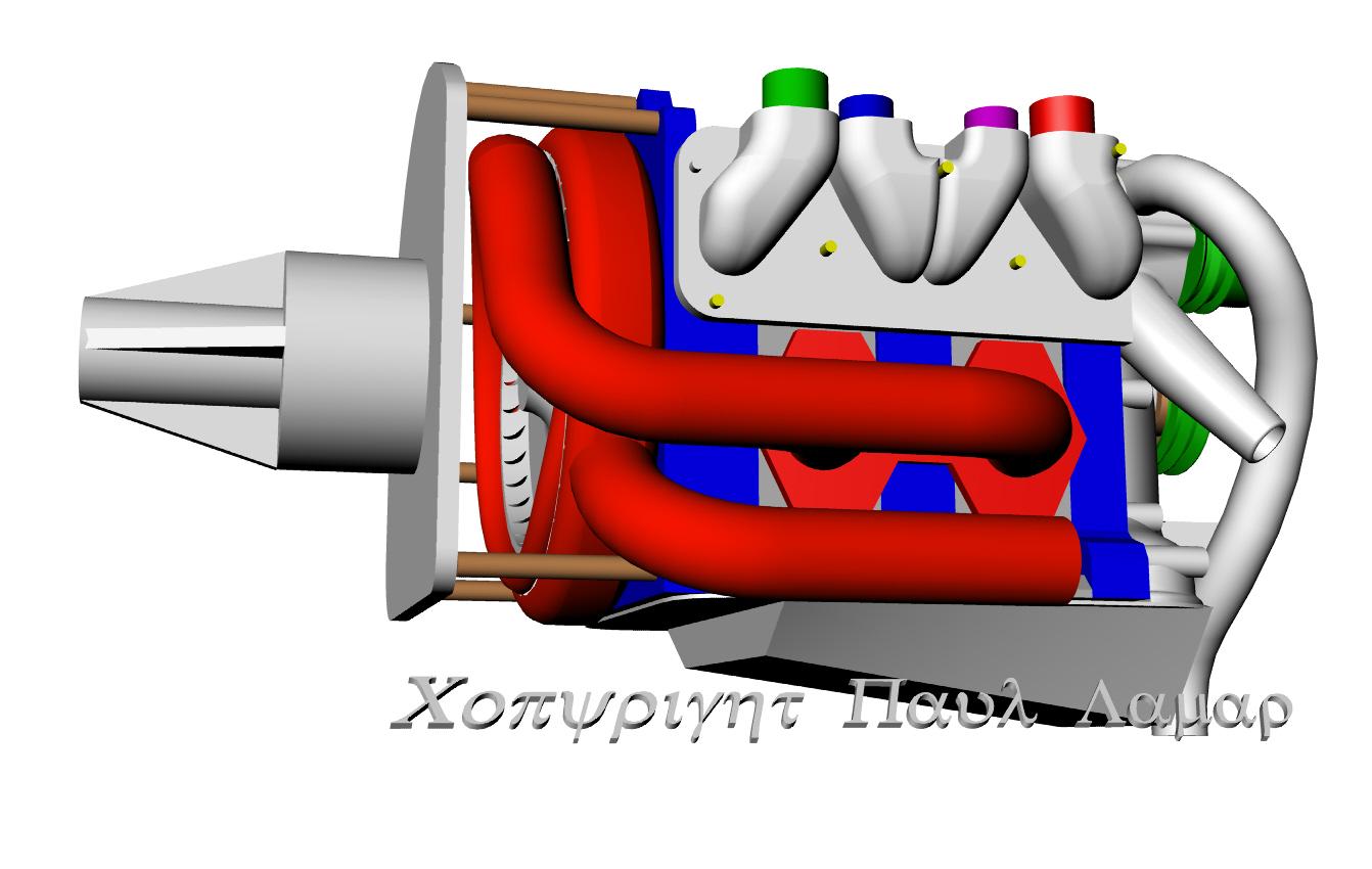
I finally got a handle on the diameter and blade length of the direct drive
turbine needed to work well with a rotary. A 19,000 RPM Formula 1 engine would
require a smaller turbine. This correlates well with the geared turbine used
on the R3350 TC engine. The 11.3 inch diameter R3350 turbine speed is 16,000 RPM
at cruise power and 19,000 RPM at takeoff power. Gear ratio is 6.52:1. Engine
RPM is 2900.
A stationary blow down turbine with air flowing over the blades generates
maximum torque. As the turbine accelerates the torque reduces in a straight
line. As the turbine blades reach the speed of the air flowing over them no
torque is generated. This will be the maximum theoretical RPM of the turbine.
The maximum HP generated by the turbine will be at a RPM that is roughly half of
the peak RPM. Torque at mid RPM will be roughly half of peak torque. Since HP is
RPM times torque peak HP is generated at half peak RPM and half peak torque
roughly speaking.
If the total projected blade area of the turbine is the same as the cross
sectional area of the exhaust pipe feeding it the velocity of the gas flowing
over the blades will be the same as the exhaust pipe gas velocity. The projected
area is that area between the inner diameter of the blades and the outer
diameter. Not the total blade surface area.
The part of the exhaust system closest to the blades is called the nozzle. It is
usually possible to neck down the nozzle area to speed the air flowing over the
blades at the modest expense of increasing the back pressure on the engine. This
is analogous to changing the A/R ratio of a turbo charger. Usually there is an
overall increase in net HP of the turbo compound system because gas velocity is
more important than back pressure. The blades respond to the gas velocity
squared just like lift on a wing responds to an increase in forward speed. The
force the blades exert on the hub is the density of the gas times the surface
area of the blades times the lift coefficient times the gas velocity squared.
Just like a wing. Lift coefficients on the highly cambered blades would be
between one and one and a half.
Since you need to keep the projected cross sectional area of the blades more or
less the same as the exhaust pipe area the length of the blades must change as
the overall diameter of the turbine changes. In general a large diameter turbine
with short blades will generate more torque and peak HP and will be generated at
a lower RPM. The up side to this is the gear ratio required between turbine and
crankshaft is reduced. The draw back is leakage around the ends of the blades.
The aspect ratio of the blades in wing terms is low. A smaller diameter turbine
with longer blades will operate at a higher RPM but the blades aerodynamic
losses may be lower due to a more favorable aspect ratio. What also must be
considered is the centrifugal loads on the blades. Longer blades put more stress
on the roots of the blades which is the critical area. Another factor of course
is metal loses it strength as the temperature of the metal increases. There is
an area of operation bounded on one side by the turbine inlet temperature and on
the other side by the RPM. these two lines eventually converge so one must keep
the turbine operating in the safe area between the two curves. Turbine design is
best left up to people with experience. One of those companies is Barber Nichols
in the US.
I used QB (below) to help with the calcs. A spread sheet would also work.
The results are in the attached jpg. The theoretical free speed of the 10 inch
turbine is 23,000 RPM. Of course the turbine would not live at that speed. This
turbine will be generating max HP around half of that or about 11,500 RPM. As
long as it is connected to the e-shaft (crankshaft) it will not see any RPM
higher than the engine. This is a racing application. For an aircraft engine
the turbine will need to be a bit bigger.
Check my logic and math.
Paul Lamar
------------------------------------------------------------------
CLS
PRINT : GasVel = 1000'FPS
PRINT "Gas Vel FPS ="; GasVel
PipeR = 1.5: AreaPipe = PipeR ^ 2 * 3.1416
PRINT "Area Pipe sq in ="; AreaPipe
PRINT
R1 = 5: R2 = 4.77
PRINT "Turbine Dia OD in ="; R1 * 2
PRINT "Turbine Dia ID in ="; R2 * 2: PRINT
FlowArea = R1 ^ 2 * 3.1416 - R2 ^ 2 * 3.1416
PRINT "Flow Area sq in ="; FlowArea
Circum = R1 * 2 * 3.1416
PRINT : PRINT "Circum Inches ="; Circum
PRINT : PRINT "Circum Feet ="; Circum / 12
PRINT : PRINT "Rev per second ="; GasVel / (Circum / 12)
PRINT : PRINT "Rev per minute ="; (GasVel / (Circum / 12)) * 60
--
The Rotary Engine NewsLetter. Powered by Linux.
ACRE NL web site.
http://www.rotaryeng.net
Youtube key word UTUBPLEASE
Copyright 1998-2008 All world wide rights reserved.