This is an interesting discussion.......
Subject: Re: Pratt & Whitney R-3350 for sale reduction ratios on PRTs
Date : 11/25/08 02:37 PM
" I would dearly like to know the step down ratio from the exhaust
turbine to the prop shaft ".........
The PRT's are unique to the 3350. When I took my FAA writtens there was
a question on it asking how much hp each made. I am afraid I cannot
remember the exact answer but would guess approx. 125 ea. They are
geared right to the crank if my memory is accurate.
I used to frequent the Save-A-Connie museum when I lived in Kansas
City. They had a cut-away R-3350 (actually TC-18) on a stand that they
could rotate with an electric motor. For some reason, the number I
recall is 150HP each for a total contribution of 450HP to the engine.
There's a lot of gearing in those big radial engines. The crank is
geared relative to the prop. The accessory case is geared relative to
the crank. The supercharger is geared relative to the accessory case.
And so it goes.
Figuring out the gear ratio between the PRT's and the prop would be a
bit of work. Suffice it to say it's a lot of gearing. The PRT's
function efficiently at turbo-charger speeds, which can run up close to
100,000 RPM. The PRT shafts run through a fluid coupling anyway. It
looks just like a mini torque converter out of an automatic transmission
in a Buick.
I would ballpark it at more than 50,000 PRT RPM for 1500 prop RPM; for
an overall ratio of more than 30:1. But the moving parts along the way
go faster and slower at each step and I could easily be off by an order
of magnitude.
Like a turbo, the PRT's are probably turning at a rate similar to the
supercharger. That's where they're efficient.
David Bunin
David-
The Curtiss Wright R-3350 972TC18DA-2 or DA-4 on the DC-7 (believe the
Connie used the R3350 972TC18EA-2) put out 3250 BHP with the PRT's
nearly 1 BHP were pound of engine. Each engine has 3 of them. The basic
engine was 2600 BHP and then they had a water injection model that
Developed either 2900 or 3000 BHP. I'll have to get out my DC-7 manual
for the exact amount of HP the PRT's provided. Some engine differences
were due to the prop on the airplane. The DC-7 had a four bladed prop
and the Connie had a longer 3 bladed prop. Prop difference was due to
airplane gear height and ground clearance.
The drive coupling for the PRT was manufacturered by Fluid Drive, Corp.,
in my home town of Holly , Michigan, a divison of Nelson
Manufacturing(Now defunct). One problem was the shaft from the coupling
to the PRT turbine was rather long and would create a whip in its
bearing and end up in a PRT failure.
The R-3350 with the PRT was an engineering miracle and a very good
engine, but not with a ham handed pilot at the controls--you had to
treat it like a new girl friend--nice . It was an injected engine and
if you advanced the throttle forward too fast you could twist the engine
accessory tail shaft that drove the injection pumps (two of them). The
engine was like an Indianapolis race car compared to NASCAR boilerplate
type car. The P&W R-2800 on the Convair 240/440, Martins 404 and
Douglas DC-6 was boiler plate compared to the R-3350.
I flew them for 11 years and never had an engine failure. Alot of
shorted secondaries and plug lead and coil changes (the system was low
tension ignition with a high tension coil and short lead on the
cylinder) but no gut jobs. Watching the exhaust flame from the top PRT
on a night takeoff was a sight to behold. When rich at takeoff power
the flames were blue orange and the length varied--when you reduced to
METO power the flame sucked right in near the PRT exhaust and was a blue
white beauty. You could set the power almost by the exhaust it.
Doug 1
182J
Dave
Thanks for the info. I think you gave me the information I needed. I was
interested in the gearing ratio from the PRT to the fluid coupling only
actually. If the coupling is actually a torque converter, which is
possible since Packhard used one in 1949, then the actual rpms going
into the converter might well be a bit higher than the engine crankshaft
rpms. It is sensible that the gear ratio relationship between the PRT
and the crankshaft would follow different power curves.
Using a torque converter (unless it locked up) would result in large
efficiency losses however.
http://en.wikipedia.org/wiki/Torque_converter
Torque converter elements
"A fluid coupling is a two element drive that is incapable of
multiplying torque, while a torque converter has at least one extra
element the stator which alters the drive's characteristics during
periods of high slippage, producing an increase in output torque.
In a torque converter there are at least three rotating elements: the
pump, which is mechanically driven by the prime mover; the turbine,
which drives the load; and the stator, which is interposed between the
pump and turbine so that it can alter oil flow returning from the
turbine to the pump."
I am trying to work out the best ratio to use after the traction drive
for my turbo compound design and I suspect on the R-3350 set-up, there
had to be a rpm mismatch and perhaps the designers assured that the rpms
going into the torque converter were always higher than the engine
crankshaft speed. This is only my opinion though and I would like to
confirm it as I am in the process for finally getting a handle on the
turbine choice and final gear ratio.
On the other hand if if just a oil dampener, or fluid coupling that
essentially locks up, then that is an entirely different design concept
and would infer that the engine and the PRT power curves a
or rpms are matched close enough.
Doug 1,
So you have actually flown behind this engine. Wonderful. Please tell
me how you went about dialing in the engine for best performance at
cruise speed and high altitude. I understand you had a BMEP guage to
aid in the process. What was the order in leaning and adjusting the
super charger deck pressure?
Doug 2 in Japan.
----------------------------------------------------------------------
Dave or Doug 1 is not on here. This message was uploaded from I don't
know where by Marc Wiese.
The R3350TC had a simple fluid coupling. Not a torque converter.
Torque converters are horribly inefficient when actually converting
torque. On the order of 65%. I know..we used to use them in our
Chaparral race cars.
Modern torque converter transmissions have lock up clutches
and these types of auto transmissions are disappearing in the world.
They are being replaced by servo shifted manual transmission. Some
with dual clutches because they are more efficient over the entire
speed range.
I appreciate the need for a variable gear ratio but I don't think
torque converters are the way to go. The R3350 TC had a two speed
geared supercharger.
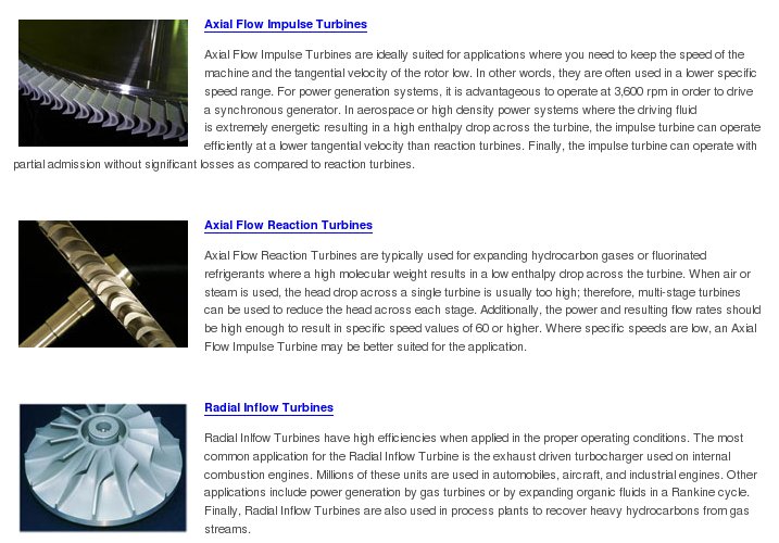
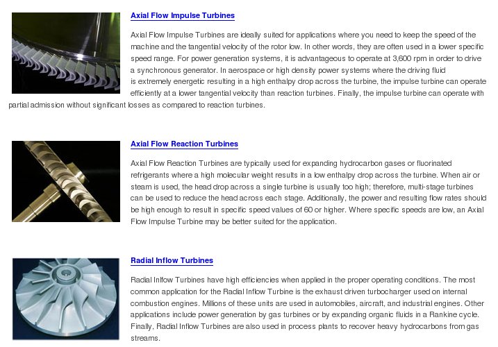
I have changed my mind about using radial inflow turbines. They
primarily work on pressure differences. Further turbine study
on my part indicates they are not as efficient as an axial flow
blow down turbines. There is still some confusion in my mind exactly
what a blow down turbine now looks like as the name has been changed over the
years. The R3350 blow down turbine looks a lot like what is now known as a
as an axial impulse turbine in Barber Nichols speak.
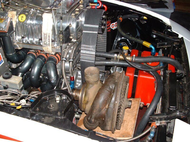
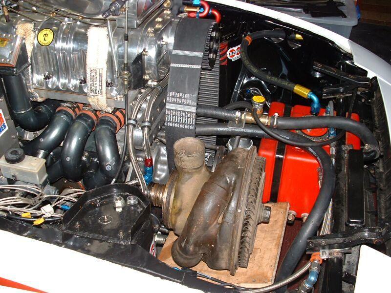
This I think is why the Scania TC is not as effective as the Detroit Diesel DD15
turbo compound engine. The Scania used a radial inflow turbine and the DD15 uses
an axial flow turbine. Radial inflow turbines require considerable back pressure
to work while properly designed axial flow blow down turbines work on kinetic
energy alone.
This is not to say a variable vane nozzle on an axial flow turbine will not
work. It will but at the expense of some back pressure.
Paul Lamar
--
The Rotary Engine NewsLetter. Powered by Linux.
ACRE NL web site.
http://www.rotaryeng.net
Youtube key word UTUBPLEASE
Copyright 1998-2008 All world wide rights reserved.