------------------------------------------------------------------
I made a few very conservative educated guesses about the conditions
inside the exhaust pipe. These can be easily verified by measurement's
which is the next step.
Gas velocity in the 3 inch diameter exhaust pipe is assumed to be 1000
FPS or 681 MPH. A variable nozzle would increase that at the expense
of some back
pressure.
Air density in the pipe is assumed to be half sea level or .0013 for
the MPH constant. That affects the dynamic pressure directly. Not to
be confused with static pressure.
Paul Lamar
Hi Paul,
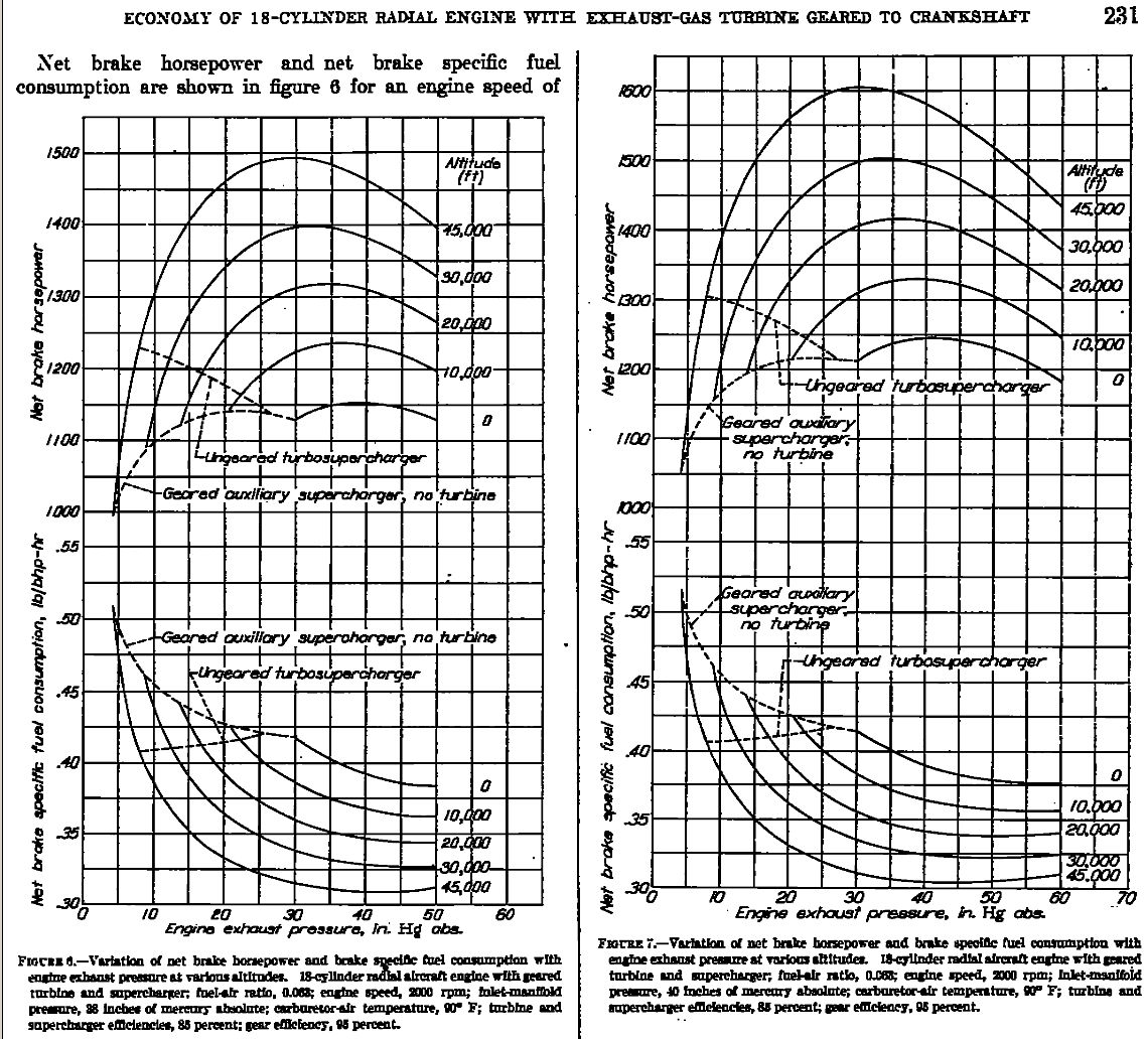
Exhaust velocity seems to be very much higher than 1000 FPS. Check this:
NACA Report No. 822:
Calculatons of economy of 18-cylinder radial aircraft engine with
exhaust-gas turbine geared to crankshaft
http://naca.central.cranfield.ac.uk/report.php?NID=2196
Page 8:
"For example, a system designed for geared operation with maximum
economy at the following conditions is considered;
Engine speed - 2000 rpm
Inlet manifold pressure - 40 InHg Abs.
Altitude - 30,000 ft.
At these conditions. a turbine with a closed waste gate and and an
effective nozzle area of 10 sq.in will produce an engine exhaust
pressure of 42 InHg Abs. and, according to fig. 7, will give a net BSFC
very close to a minimum (ie. 0.33 BSFC). For expansion from 42 InHg Abs.
to atmospheric pressure at 33,000 ft., the theoretical turbine-nozzle
discharge velocity is 3115 fps. For a turbine wheel pitch-line velocity
of 1200 fps, the corresponding blade-to-jet speed ratio is 0.385, which
gives an efficiency close to peak value for a single-stage impulse
turbine. The turbine should be equipped with a gear train to provide the
correct pitch-line velocity at an engine speed of 2000 rpm."
Cont. on Page 9:
"The range of satisfactory compound operation could be greatly increased
by the use of a variable gear ratio between the engine and the
turbo superchrger, variable turbine-nozzle area, and variable diffuser
vanes to prevent supercharger surge."
Cheers,
Petri
Yes I have that NACA paper. Here it is. do you have a better copy? I'll
put it
on the web site for download.
I was trying to be conservative with my calculations.
Trouble is it is high altitude orientated which is good for aircraft
but not so hot for sea level. Pardon the pun :) It is early work test stand
and Curtiss Wright added to the practical knowledge base later on.
Curtiss Wright moved away from the pressure turbine to the blow down
turbine
and average back pressure on the engine was reduced to 2.8 psi above
atmospheric. That would be about 36 inches of Hg if my arithmetic is
correct.
Curtiss Wright claimed exhaust gas velocity was 2200 FPS 1.9 Mach, 1500
MPH,
214 Km/hour on the R3350 TC. I was amazed. What happens to a turbine
blade when it is struck by a 2200 FPS blast of supersonic 1500 F,
815 C gases ? :)
>
> Paul Lamar
Yes, but remember, speed of sound is temperature-dependent - temp goes
up, Mach goes up. Relation as m/s is Vmach = 20.05 * SQR(T) (T=kelvin)
Thus, Mach 1.0 speed relative to temperature is:
59 F = 15 C = 288 K = 340 m/s = 1116 fps (std. atmo)
150 F = 66 C = 339 K = 369 m/s = 1210 fps (charged intake max)
1500 F = 815 C = 1089 K = 662 m/s = 2170 fps
1600 F = 871 C = 1144 K = 678 m/s = 2225 fps
1700 F = 927 C = 1200 K = 695 m/s = 2280 fps
1800 F = 982 C = 1255 K = 710 m/s = 2331 fps
So, our 2200 FPS on 1500 F turns out to be 2200/2170 = 1.01 Mach!
This is so close that i believe the inflow was actually just barely
subsonic.
Then - what's interesting for us, how much BSFC gain did they got at sea
level - and how much would valveless rotary get? by interpolating from
data on this study?
Looking the Figure 7, on sea level curve, from 30 in hg abs - ie. sea
level pressure to 50 in hg abs, ie 20 in hg (0.67 bar) back pressure the
BSFC goes from abt. 0.42 to 0.38. That's 9.5% gain on BSFC.
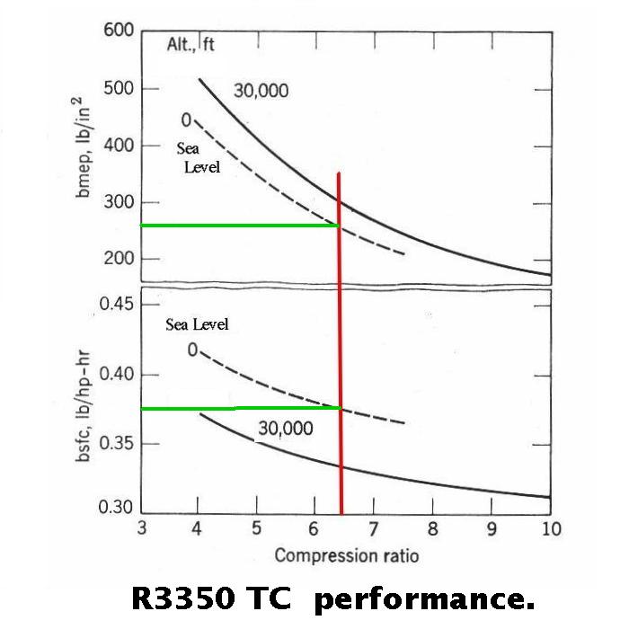
If we think that we have a better turbine and less flow resistance, and
thus omit the -50% poppet valve flow reduction completely (indicated by
3350TC graph), we might have 19% gain on sea level.
If we start from 0.47 we get thus 0.47*0.81= 0.38 BSFC.
And if we can lean the engine to 0.44 first, we got 0.44*0.81= 0.36 BSFC.
Not bad. Definitely a worthwile project :)
Armchair engineering of course, but direction is quite clear.
Main challenges seems to be:
- Get proper flow simulations to get the right design.
- Do the test rig runs to verify it
- Make efficient but cost-effective reduction gearing
- Design a torque pulse damper
- find a sensible installation place for the assembly
- and get this thing to work from 100% takeoff to 55% economy cruise on
altitude.
- Design for manufacturing, flight test, and make aviation history ;)
Since the benefit from TC is higher at altitude, it would be best to
have a pressurized test aircraft to create some real PR by some show-off
record flights. Like Lancair IV-P or Aerostar 700P. Cessna Skymaster
P337 is also cool, but maybe a bit slow compared to IV-P and 700P.
When it's ready?
I think i can promise to complete this project on my own money and spare
time... um... let's say, within 12 years?!?
This TC project obviously requires a concentrated team effort...
I guess some might think that:
"why not just slap a suitable turbo on rotary exhaust and replace the
compressor side with rotrex, and load it with eg. v-belt driven
varipitch ivoprop?"
Yes, why not... anyone?
Cheers,
Petri
The Rotary Engine NewsLetter. Powered by Linux.
ACRE NL web site.
http://www.rotaryeng.net
Youtube key word UTUBPLEASE
Copyright 1998-2008 All world wide rights reserved.