Paul,
Fluidyne PowerSport can supply the cores I need for the folded core
cooling block. I'm having a harder time finding somebody that can
fabricate it.
While I'm in that process, I'm taking another look at your two pass heat
exchanger. Here are my questions:
Q1. What determines the size of the gap between the to cores? What gap
would you recommend as a
_minimum_ for a core sizes of 14" x 12"?
Q2. I assume you don't want air leaking out of the gap between the cores
before it gets to the rear core. In your book, you recommend phenolic or
fiberglass for supporting the two cores, so I guess that non-conductive
material would be good to close the gap between the two cores, too.
Q3. Can the tanks of a heat exchanger be on the ends rather than top and
bottom?
Q4. What would be the absolute
_minimum_ distance from the face of a 14"
x 12" core for a trumpet diffuser?
Q5. Do I understand what you're saying in your book (Fig. 12-11, the "A"
distance in the upper graph) correctly, if I can't extend a trumpet
diffuser to optimum distance from the core face, then I should size the
diffuser opening according to Table 12-1, Coordinates of Streamline
Diffusers, at the appropriate distance on the left column. For example,
if I only have 12" for a trumpet diffuser, then the width of the opening
for a 40% intake would be .510 times the core height.
Q6. You recommended 35% intakes for the wedge type diffusers in the
cooling block design for my cruise speed (130 mph). Would 35%
intakes also be a good ratio for a trumpet diffuser for a 14" x 12" two
pass core face?
Q7. What would be the minimum room required behind a 14" x 12" core heat
exchanger.
Thanks for you help,
Sandy
I think you are talking about the cross counter flow configuration.
First of all you would be lucky to get a 10% volume reduction with this
configuration so I don't think it will work alone for the glass goose. Having
said that all you need is a 1/4 inch between the cores. The idea is not to let
the front rad touch the rear rad.
Q2. correct.
Q3. the tanks should be on top and bottom as that puts the cores in parallel
which is what you need. On ends would put the cores in series. Easier to weld
but no where near as efficient. In other words too big?
Q5. correct. If taken to the logical conclusion zero lenght means the core
is sitting out there like a WW 1 airplane. I see no way to use a K & W diffuser
with the glass goose.
Q6. yes on 35% but no way is 14 by 12 going to work on the goose even with
the counter cross flow design.
Q7. about six inches but again 14 by 12 will not cut it.
Welding the folded core design can be done if one plans ahead.
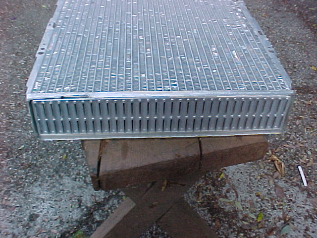
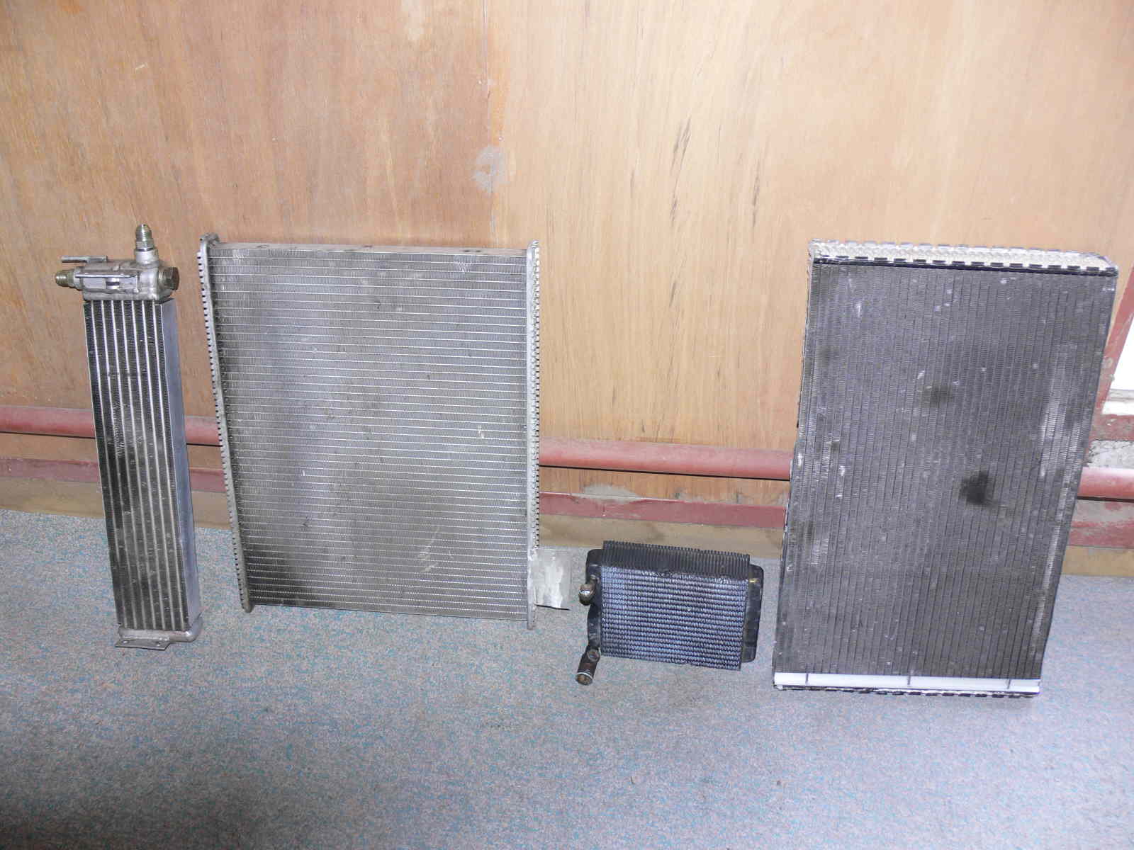
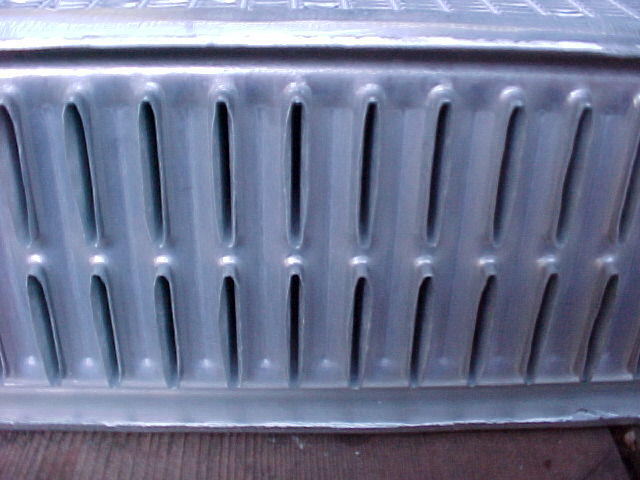
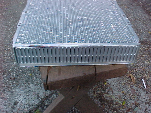
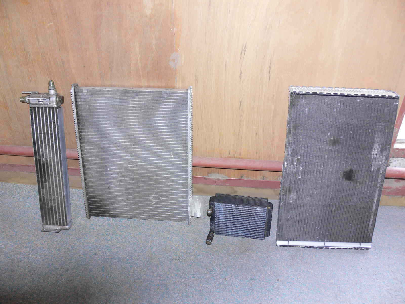
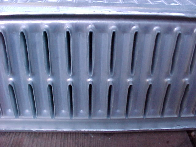
I have to work on a 3D on how to do that. As you can see from these pictures
of rad cores with the plastic header thanks removed there is a complex folded
flange around each end. The holes you cut in the top and bottom plates are just
large enough to accommodate the out side dimensions of these flanges. It is
then easy to weld them to the top and bottom plates from either
side of the plate.
If the rad manufacture truly makes his own cores by furnace brazing the tubes
directly into the top and bottom plates this is not necessary. I suspect
Fluidyne may not be doing this and merely buying brazed cores from some other
manufacturer.
Do you have flying privileges? You could find a rad factory in China
and start a biz selling folded cores in the US :) Internet advertising is
real cheap. Most rad cores are now built there anyway.
Paul Lamar
--
The Rotary Engine NewsLetter. Powered by Linux.
ACRE NL web site.
http://www.rotaryeng.net
Youtube key word UTUBPLEASE
Copyright 1998-2008 All world wide rights reserved.