Hello Steve,
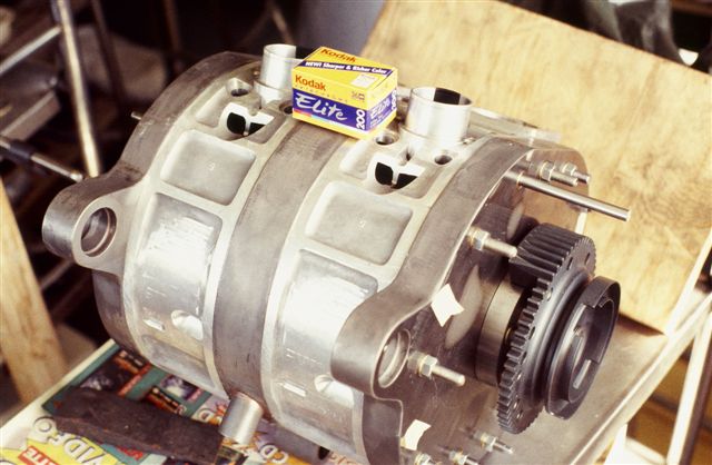
In the picture shown there are passages around the intake pipe. Could
you comment on what those were for. Is that gear teeth surfaced item on
the front a counterweight that also drives acessories? If so very
clever. You talked about the coolant routing on a previous email but
didnt get to specific. Could you comment more on the coolant path of
that engine. I undersatnd that the entrance water hits the plug bosses
but how does it axially flow to the exit. Is the centerhousing a circum.
flow design?
Rob Woods
Rob--my apologies for now getting back earlier to you with responses to your
questions.
1. Passages around ports. What you see in the photo is machining related to
installation of the throttle shafts and levers....with shafts, levers and
butterflies not yet installed.
2. Counterweight--nice deduction on your part. This one part machined from
steel billet served several functions-- eccentric shaft counterweight,
starter ring gear, trigger wheel interruptor segments for the infared
electronic ignition modules and v-belt drive for accessories.
3. Coolant--cold water entered the spark plug cooling jet manifold and
flowed axially from center housing. If you don't have the other photos
showing the various water and oil hoses and routing, I can get them to you.
Steve Beckham
--
The Rotary Engine NewsLetter. Powered by Linux.
ACRE NL web site.
http://www.rotaryeng.net
Youtube key word UTUBPLEASE
Copyright 1998-2008 All world wide rights reserved.