I slapped my forehead when I figured this out.....DUH!
Considering the present cowling shape, I studied a variation of your
folded core cooling block. How about one fold....actually, two
radiator cores with a common tank between them in a vee
shape.....intake port at the top and exit port at the bottom. Scott
Gettings keeps going back to this plan, but the problem was fitting
the vertical radiators in a gradually sloping cowling. Then it hits
me...why not give the vee shaped radiators a 90 degree flip. Now,
we've got a ton of room for cooling core because it lends itself to
the cowling shape (see One fold horizontal radiator (Large).jpg). We
have enough room now put more cooling core for water AND oil than we
need. With the rads mounted vertically. it adapts well to wedge
diffusers in a traditional shaped horizontal intake.
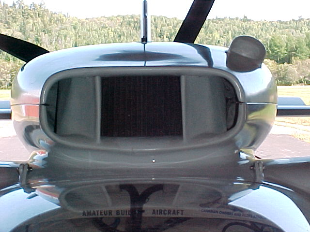
I've also included some views of the cowling. Note that there is a lot
of exit air room down both sides of the engine (see Cowling rear
(Large).jpg)
In the attached file (One fold horizontal radiator - Thicker Core
Numbers (Large).jpg), there are some numbers for 1.75" and 2" cores.
Q1. What do you think about this plan? What adjustments would you like
to see?
Q2. The 1.5" core offers about what the RX8 has in cooling. Would that
be enough? I sure don't want to overheat in the summer on a Texas
taxiway. If there is any doubt I'd rather have the cooling drag than
the
heat.
Q3. Can the top intake port and the bottom exit port be on the same
side of a radiator, or is it best to have them on opposite sides?
Thanks for you thoughts
Sandy McNabb
Renesis in a Glass Goose
Looks like it will work fine if you put the tanks on the sides instead
of on the ends. That way top and bottom rad will be in parallel
instead of series.
I talked to the president of Fluiddyne and he was not interested.
I think he was feeling the down turn, He wanted a minimum of 12 cores
12 by 12 by 1 at $300 each. They are worth $100 each at the most.
In other words $3600. He was not familiar with thermo principles.
The engineer if any was not there.
I found a company in Brisbane Aus that understood what we were trying
to do and agreed to make us anything we want including mounting the
tubes at an angle so they are aligned with the air flow. The exchange
rate is good with Aus and George Lendridge lives in Brisbane.
The company is PWR 103 Lahrs Road Orrneau Queensland 4208 The guys
name is Matt Bryson 61 7 55547 16111 Email is matthew@pwr.com.au
More on this when I get home.
Paul Lamar
Paul,
How did you get onto this chap?
Do I mention your name?
I'm on to it first thing Monday.
Looks like he's in a large Industrial area, half way between Brisbane and
the Gold Coast. Lahrs Rd. is a feeder road running parallel with the
Freeway. Although I won't be able to visit him as I still can't drive for at
least another 2 weeks. However a phone call to touch base doesn't hurt.
George (down under)
They had a booth in the Performance Industry Trade show in Orlando Florida.
Matt is a very knowledgeable guy. He has the Kays & London book Compact Heat
Exchangers so he immdiately knew what I was talking about.
I showed him my Book on How to Cool Your Wankel.
He said he was going to buy a copy. When I get home I'll email him and tell
him you will call. I'll just copy this email to him right now. His last name
is Bryson.
This works two ways guys. If they help us out we should put a PWR decal on
the airplane. I learned this at the show in a seminar.
Paul Lamar
Hey Paul,
Thanks for copying me on this email, and your kind words below.
I would be interested in seeing some of the drawings,sketches or photos of
your intentions for this project.
Hope to hear from you soon.
Kind regards,
Matthew
PWR
P.S I am flying out of Orlando on Sunday and have some business to do back
in Sydney Australia on Tuesday before returning home to Brisbane. I will be
back in the office on Wednesday.
Thanks Matt here is what Sandy has in mind. It is best if the rads are in
parralle.
Paul Lamar
==================================================
Hello Paul,
I'm looking at this cooling design (new version with 2" cores attached) as
one water heat exchanger (13.333" x 24" x 2") and one oil cooler (6.666" x
24" x 2") folded in the middle.....not four independent coolers. There are
major problems with putting the tanks on the ends:
1. Putting the tanks on the ends locates the tanks in the intake area which
reduces the horizontal area available for intake diffusers. With the tanks
on the top and bottom the whole 20" is available for the diffuser. Tanks on
the ends takes out 1.5" (tanks) x 4 (coolers) = 6" less horizontal area for
diffusers which causes a significant increase in the vertical dimension of
the diffusers, not to mention the 3" gap left between the coolers in the
front.
2. Putting the tanks on the ends also cuts the cooling core by 24 cu ins
(Tanks on top and bottom: 20" x 1.5" (tank size) x 2" (core) x 2 (tanks top
and bottom) = 120 cu ins. Tanks on the ends: 24" x 1.5" (tank size) x 2"
(core) x 2 (tanks on the ends of coolers) = 144 cu ins).
3. The plumbing is approximately doubled when treated as four independent
coolers....I think.
Where do I go now?
Thanks,
Sandy McNabb
Renesis in a Glass Goose
Everything is a trade off when it comes to heat exchangers. It will
certainly function that way but the question is; how well? Heat transfer is
a strong function of the temp difference between the air (100F) and the rad
(200F). As the coolant flows in the top rad and down through the bottom it
cools off so the bottom rad is not as good at transferring heat to the air.
The rule of thumb is one degree drop in the temp. difference is one percent
drop in cooling. Another rule is the first half does 3/4 of the work. If
both are the same temperature using side tanks total heat transfer is
better. The side tanks can be tapered.
Thicker at the back (1.5 inch) and thinner at the front (0 inches).
I would be guessing on how much the difference is.
Here are a couple of pictures from F1. They are spending more money on R&D
on this subject than anyone.
On the oil rads you have no choice as they do not lend themselves to being
welded together and if attempted it could be disaster due to the 150 psi of
the rotary engine oil when cold if a weld fails.
You could cock the oil rads at some small angle to take advantage of the
widening cowl. I suggest plumbing those in parallel as well.
Perhaps Matt Bryson has some thoughts on this as he knows far more about it
than I do.
Bottom line is; it is always up to you and what you are willing to try.
Paul Lamar
=================================================
Hello Paul,
You have definitely confirmed what I was concluding in my own mind about
cooling when you say above, "Everything is a trade off when it comes to heat
exchangers." Here's my problem.....I've read your book, studied your site,
and been paying attention to this blog, so I think I know the more important
cooling principles. What I don't know is when it comes to compromising two
principles, which one is more important (i.e., Is running parallel more
important than the 30 cu ins of cooling core loss to do it (in my case), or
is it more important to have thin radiators or less frontal area, and on and
on.)? Just like everybody else I want the best cooling system possible
allowing for all my limitations. I'm just not smart enough to evaluated the
compromises involved. So, the best thing I can do is to show you what I'm
doing and let you and anybody else take your best shot at it. I'd rather
make my mistakes on paper.
So, I've attached my new plan with heat exchangers in parallel as you
recommended (see One fold horizontal radiator with 2 inch cores - plumbing
(Large).jpg attached). As you can see there is now plumbing shown. It's just
where I'm starting. I've looked for the rationale in your book about
parallel versus series and I don't see anything. Would you give me a brief
reason?
Q1. You said to put the tanks on the ends and run them parallel. I can
easily run them parallel, but putting the tanks on the ends creates problems
and eliminates cooling core. Is running the HXs parallel the important
thing, or putting tanks on the ends, or both?.....one of those compromise
things again.
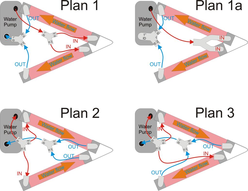
The other file (see One fold horizontal radiator with 2 inch cores -
plumbing (Large).jpg attached) addresses plumbing possibilities in order to
better illustrate my questions.
Q2. I like Plan 1a the best. The water pump exit is very close to the tank
on the top heat exchanger (HX). It's so close that I don't think there is
sufficient room for a hose of much length. I'm planning on mounting the HXs
to the top of the wing on rubber cushions and not attach it to the engine
other than silicone hoses, so I think I need the room for some hose
flexibility that Plan 1a offers. Also plumbing fixtures and tanks on the
water intake side of the HXs in Plan 1a could be welded together since they
will be having the same temperature of water entering. The problem with Plan
1a is that don't know if there are plumbing fixtures available for it. The
exit port on the water pump is 1" ID and 1.25" OD. The intake port is 7/8"
ID and 1.25" OD. Since the output to the HXs are 1" ID, I'm planning on
splitting the 1" to two 3/4" ID hoses. The two 3/4" hose areas are little
bit more area than the 1" hose area. Are there plumbing fixtures that will
accommodate that split or can welders do the job? I'm thinking that it could
be welded directly to the HX ports to eliminate connections.
Q3. Does it make any difference which way water is routed inside the HXs
(bottom to top, side to side)? I think I've read that some race cars run
their water from bottom to the top of the HX.
Q4. I measured the water pump exit (1"ID) and return (7/8" ID). Do you
recommend that I continue with those dimensions in my plumbing in and out of
the HXs?
Q5. I was studying my intake diffusers and wondering about the affect of
increase angle of attack and air flow on the intake during takeoff and
climb. Is that a valid consideration or am I just smashing ants.
'nuff for now. Thanks for your thoughts,
Sandy McNabb
Renesis in a Glass Goose
----------------------------------------------------------------------------
I can't get any closer than that. Lacking high price simulation software heat
exchangers are as much trial and error as they are science. The differences are
very small. We also have to work with the cores that we can buy at low cost.
Q1 The side tanks just clean up and simplify the plumbing.
Q2.& Q3. I like plan 3 as gravity helps the water flow. The same as the RX7.
You will need a filler neck with a pressure relief valve cap to the overflow
tank mounted near the top of the cowl. Water flows out the top hole near
the pump from the block and into the bottom hole and into the pump intake.
Q4. I would stick with what Mazda is doing as the larger hose sizes keep up
the flow velocity in terms of GPH as much as possible. In other words the
resistance of the system to water flow is lower. The pump does not have
to work as hard. Less likely to get cavitation.
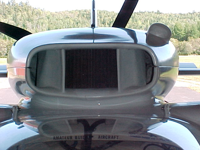
Q5. Angle of attack may cause separation on the air intake. What you have
going for you is the canopy falls away rather fast in front of the scoop.
Usually aero engineers would put a boundary layer bypass under the scoop
as in the last picture. Tape some tufts on the top of the transparent
canopy and look up on take off. If air is not flowing into the scoop try some
vortex generators.
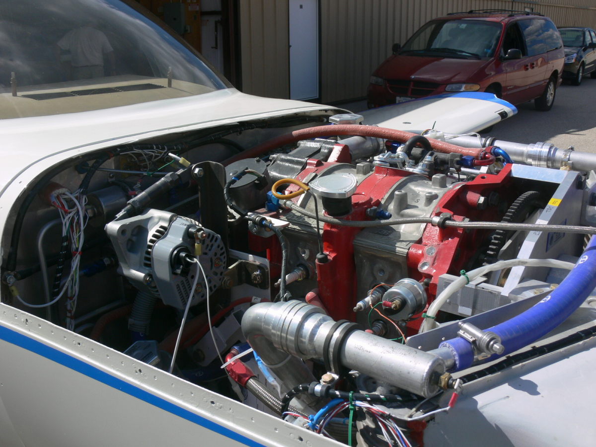
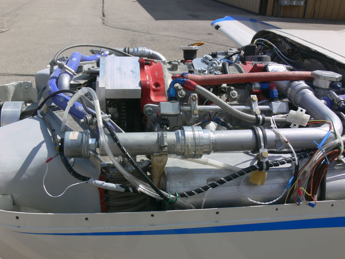
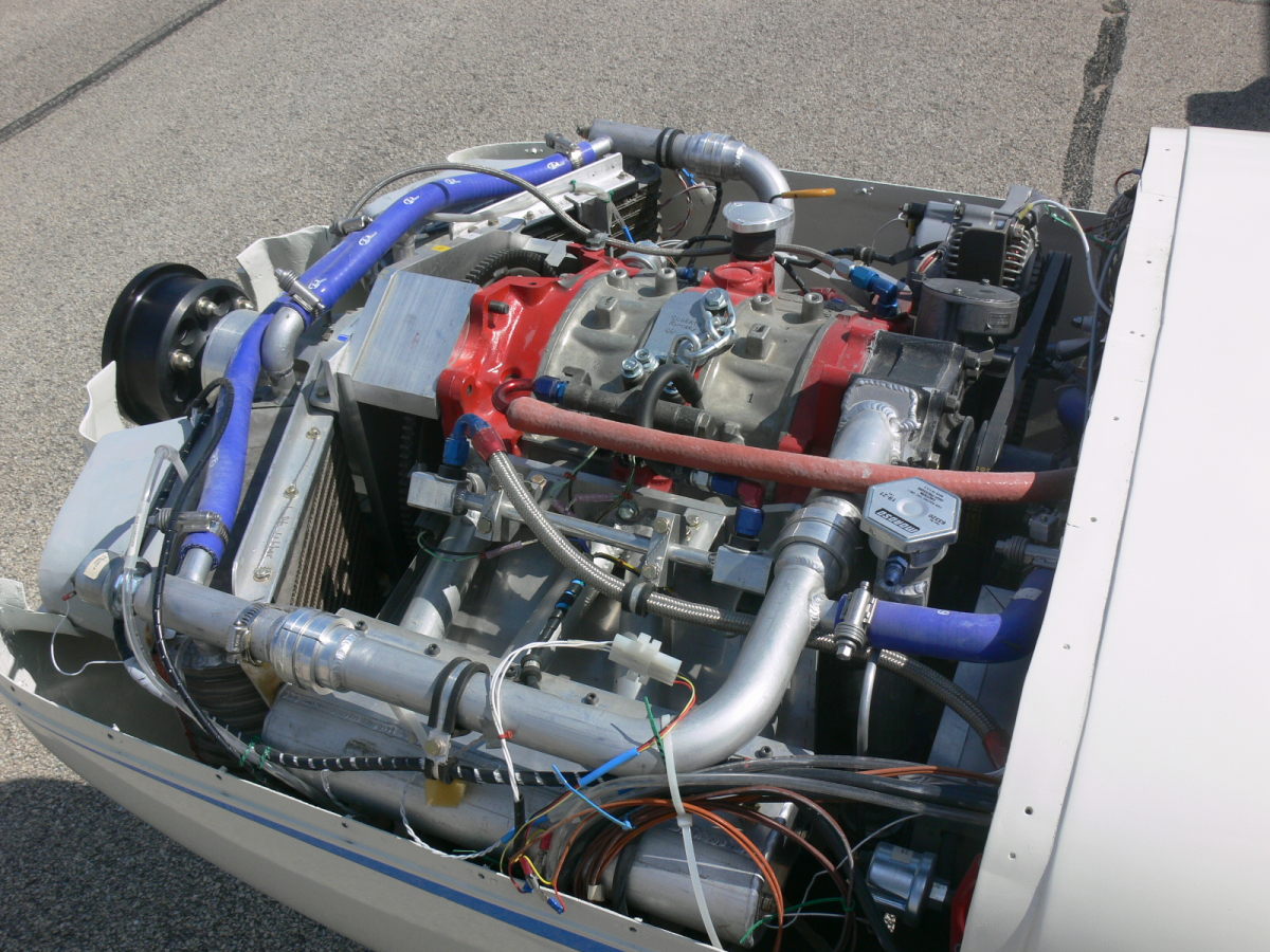
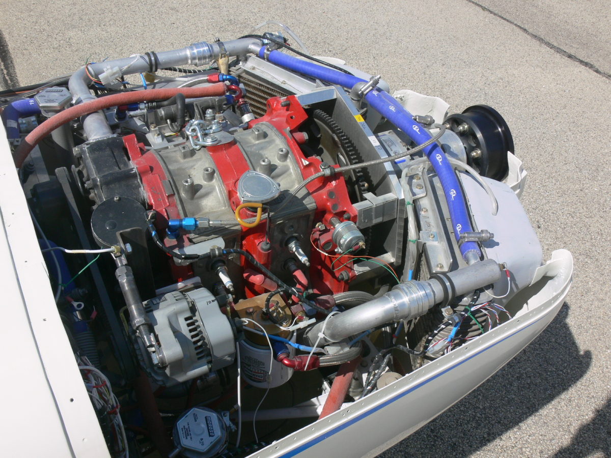
IMHO Bill Schertz is the best thermo engineer I know building an airplane and
here is what his plumbing looks like.
Paul Lamar
The Rotary Engine NewsLetter. Powered by Linux.
ACRE NL web site.
http://www.rotaryeng.net
Youtube key word UTUBPLEASE
Copyright 1998-2008 All world wide rights reserved.


.jpg)
.jpg)