Hi Paul and all
I'm working on the exit air strategy on our Glasair SII RG. Renesis 4 port
I'm comfortable that a good cowl flap/s can increase exit area substantially
from the minimum required at cruise so I'm not worried about maximum cooling
etc. it's the minimum area to reduce drag that I am considering here.
Is there an agreed ratio of inlet area to minimum outlet area?
I measured a Glasair 3 and the minimum outlet (Cowl flap closed) appear to
be approx 130cm^2 and the inlet approx 180cm^2 (There are two of each).
So Outlet = ~0.75 x Inlet (again with cowl flap closed)
Now I understand Boyles law would dictate that volume is going to increase
with temperature, and this could be calculated, however I'm not sure as to
the relationship between inlet velocity to outlet velocity.
Is there a rule of thumb for inlet to outlet?
Thanks
Steve Izett
Perth Western Australia
Yes there is. I think it is something like .8. The idea here is to recover
some of the waste energy in the cooling air and squirt it out the back
to provide thrust. Hopefully this will off set the cooling drag.
I discussed this a bit in my book "How to Cool Your Wankel".
Here is a graphic of a P51 system so designed. This is why it is widely
thought that a liquid cooled system with a dedicated exit duct can
be lower drag than an air cooled engine cooling system.
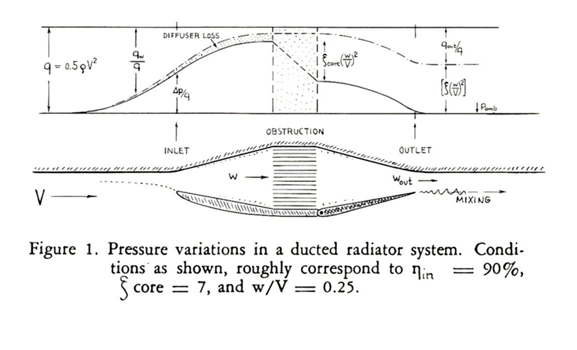
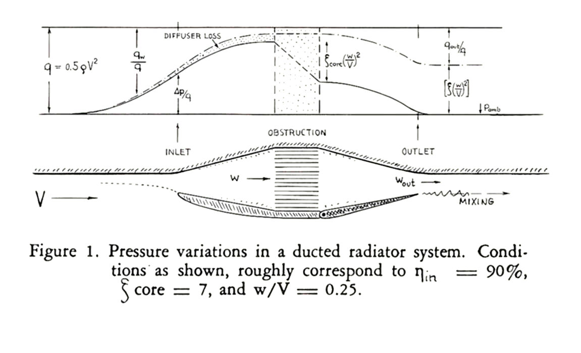
Here is a bit of theory from Hoerner's book "Fluid Dynamic Drag".
"V" is the flight speed of the aircraft.
"w" is the speed of the exit air.
In order to get thrust and reduce drag this ratio must be in the
range of zero to .15. If V is 200 MPH then the exit speed
of the cooling air should be .15 = w/V or w should be less
than 30 MPH. To me this is counter intuitive. I would think
the exit speed of the cooling air should be greater than the
forward speed of the aircraft. Here are the first two pages and
definitions of Chapter IX from Hoerner's book.
However the exact optimum exit area is highly dependent on many things.
That is the reason airplanes use adjustable cowl flaps.
You close the flaps until the engine is still running at an acceptable
temperature. Only one rotary installation I know about uses thermocouples
located near the combustion chamber and that is Mark Steitle's
3 rotor powered Lancair ES. It is probably possible that the coolant
will boil before the metal temperature in this area reaches the 500 F
limit so coolant temperature alone could be the real limit. One reason
to use as high a pressure cap setting as possible as this will raise
the boiling temperature. In an air cooled engine of course metal temperature
is the only limit.
The exit duct itself is probably the primary factor. If you
are dumping hot air out of the heat exchanger into the engine compartment
it must make its way out past the engine and gather it self together
just before the exit slot. There is an efficiency associated with this
process. There could also be leaks in the cowling which is highly
likely. The area around the exit slot in the cowling should have
a large radii to enhance the flow.
-------------------------------------------------
This is a really interesting graph from Hoerner that sums up the entire
cooling drag situation. It is obvious from the graph why a thin heat exchanger
is desirable as long as it does not increase the aircraft total frontal
area. In other words getting the heat exchanger basically mounted inside
the existing cowl. The thinner the H.E. the lower the drag.
The other very very interesting part of it is the shape of the diffuser itself
shown in the lower diagram. That old fashioned shape of diffuser has been
discredited by Kuchemann & Weber in their book Aerodynamics of Propulsion
published in 1955 and discussed in my book. For some strange reason Hoerner did
not talk to K & W during WW II. Apparently Hoerner did not have a need to know :)
The other thing missing in the lower diagram is the boundary layer air bleed.
Don't copy it.
Paul Lamar
--
The Rotary Engine NewsLetter. Powered by Linux.
ACRE NL web site.
http://www.rotaryeng.net
Youtube key word UTUBPLEASE
Copyright 1998-2008 All world wide rights reserved.