Paul,
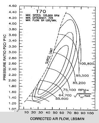
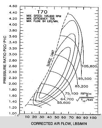
Would a T-70 turbo be a good choice for a/c use?
Mark S.
It is getting hard to find info on the old T numbers.
Garrett acts like they never existed and changed all the numbers
with their new line of turbo's.
The compressor looks fine.
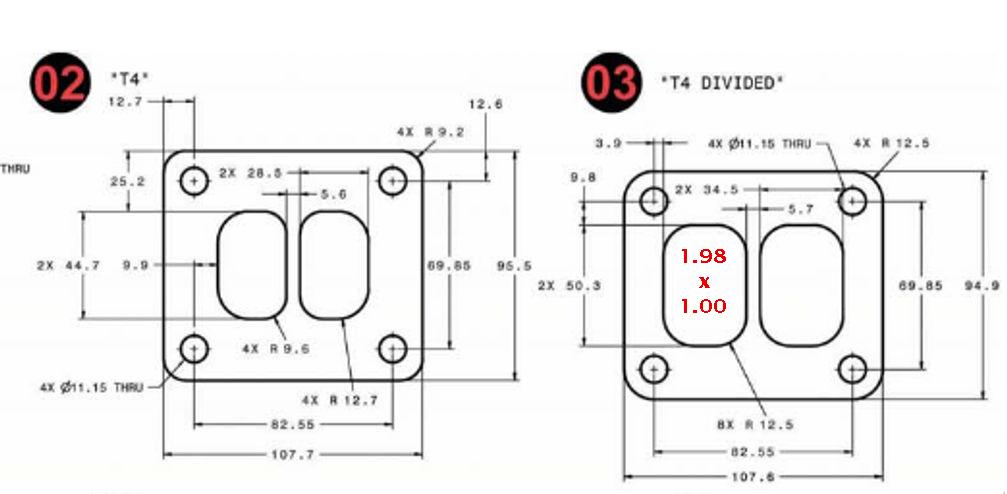
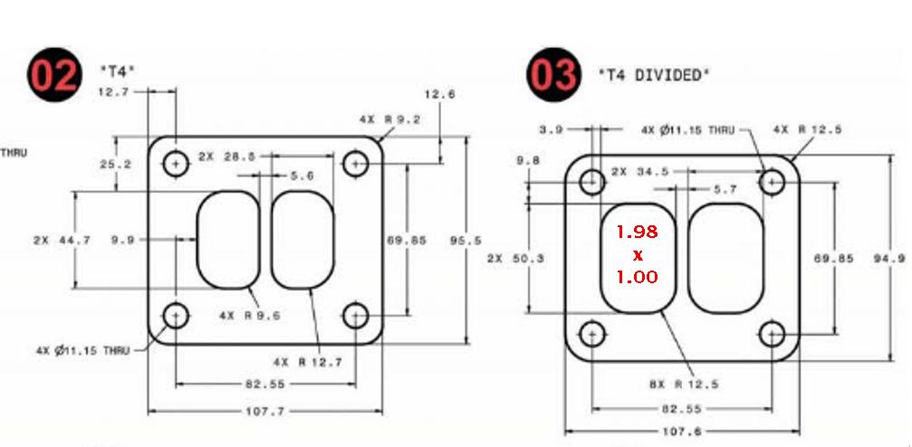
We need the A/R on the turbine. The flange is probably a T4 "divided".
You need to calculate the area of all three exhaust ports
and compare that to the area of the area of the hole in the input flange
of the turbo charger turbine. Each rotor housing port is about 2 square inches.
Six square inches total. Velocity out at full chat is 1100 fps as a first guess.
That is the first basic info for evaluating the turbine. The pipes are
probably larger than the area of the ports so the gas velocity will be reduced
in the pipes and into the turbo charger hopefully. Then the A/R must
be known. If it is "one" the gas velocity going into the blades
will be the same as the velocity going through the flange.
Looks like a T4 divided flange is on the small side for a 3 rotor.
The old undivided TO4 flange hole area was 2 by 3 or perfect for a 3 rotor
at six square inches. Yes the exhaust pipes are larger in area and will
slow the exhaust gas velocity but it will be speeded up again as it goes
through the turbo charger flange hole.
For an aircraft an A/R well over one is good. Hopefully the A/R will be
much larger than one. You will probably need a large waste gate.
Next is the diameter of the turbine. That will give an estimate of
the max speed of the turbine blade and RPM with no load. Half of that RPM will
be the max HP RPM of the turbine. You can then compare that RPM to the RPM
and flow of the compressor.
This is my best guess at my current level of research on this subject.
Paul Lamar
--
The Rotary Engine NewsLetter. Powered by Linux.
ACRE NL web site.
http://www.rotaryeng.net
Youtube key word UTUBPLEASE
Copyright 1998-2008 All world wide rights reserved.