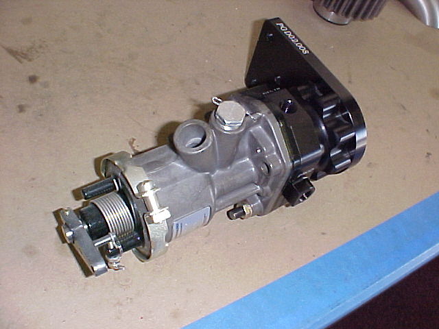
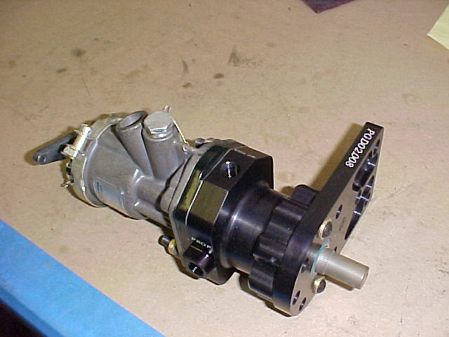
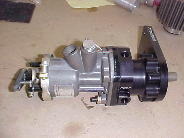
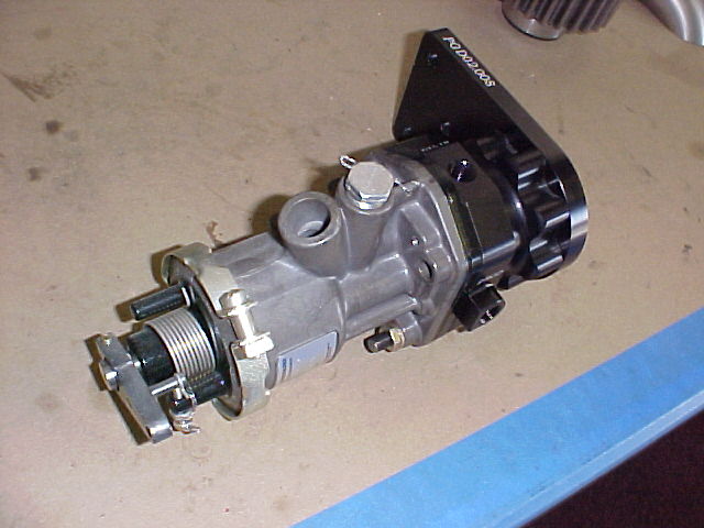
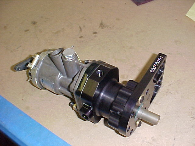
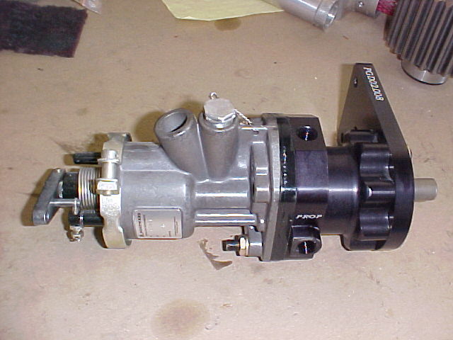
Don is also building a Mustang II as well as a Berkut.
He has designed and a friend machines his own PSRU's.
I don't know where he gets all the time.
Paul Lamar
Paul,
Tried to read the figure provided. It does not take magnification
well. Any chance you might have a more detailed schematic, or even
better, a set of plans? Do you have more information on the rubber
flex connector?
Thanks,
Gordon
--
Try these three DWGs. Let me know if you need them in some other CAD
format.
The coupling is a Lord. Here is a pdf of their catalog. The one Don
has is
a bit stiff so you probably need a softer one to get the idle RPM
below 2500 engine RPM.
Paul Lamar
Thanks Paul!
I am in your debt.
Gordon
Thanks to Don.
BTW can you send me a larger screen capture jpg of the DWG? Rhino
won't import
those DWGs
I think he is doing another design with a hollow
shaft for a constant speed prop. There is real need for that.
Paul Lamar
Dear Paul:
Sorry, I just lost my mental picture here. (Yes, I know: I should
return myself to the State Mental Facility from which I escaped).
But, before I do that, I have a question: When you wrote: " . . .
another design with a hollow shaft for a constant speed prop. There is
real need for that" are you saying that the hollow shaft design he is
working on has a hollow e-shaft, for something like a counter-rotating
shaft to the propellor to pass through the engine? Or are you referring
to something else?
Thanks!
Les Nordman :-)
Hydraulic controlled constant speed props require a hollow prop shaft
to send oil pressure to the prop that controls the pitch.
Paul Lamar
-------------------------------------------------------------------
http://www.thaitechnics.com/propeller/prop_control.html
Constant Speed : If an engine driven governor is used, the propeller will operate as a constant speed. The propeller
and engine speed will be maintained constant at any r.p.m. setting within the operating range of the propeller.
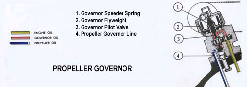
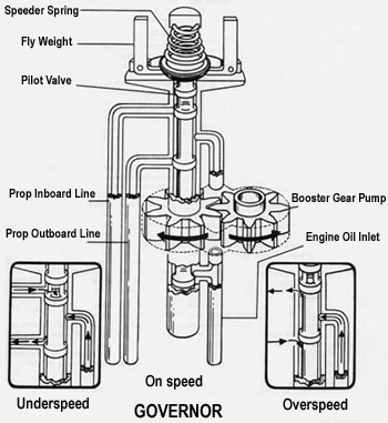
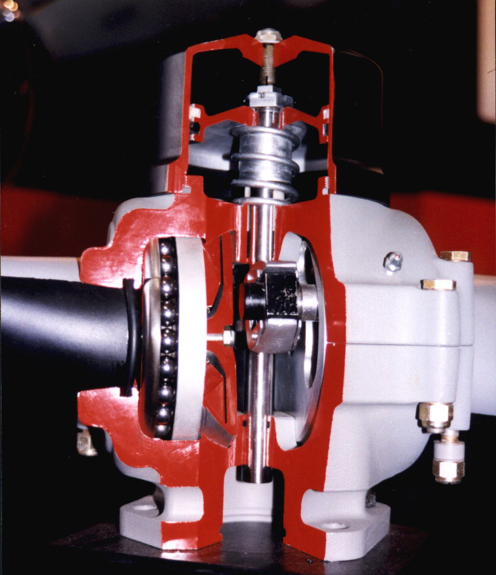
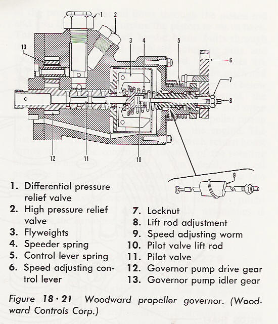
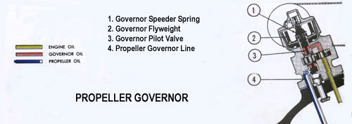
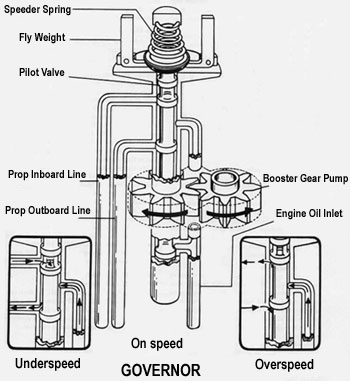
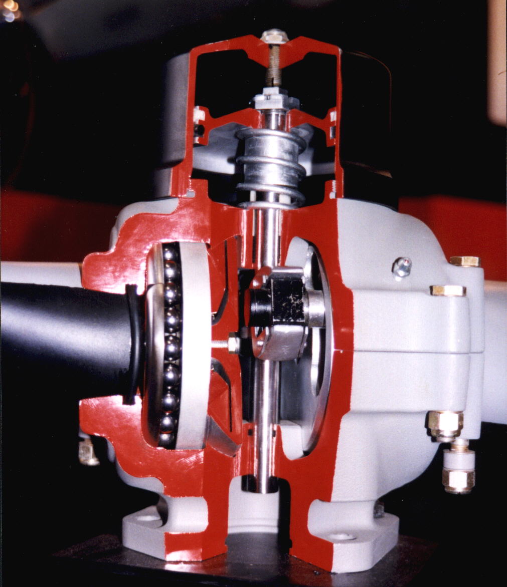
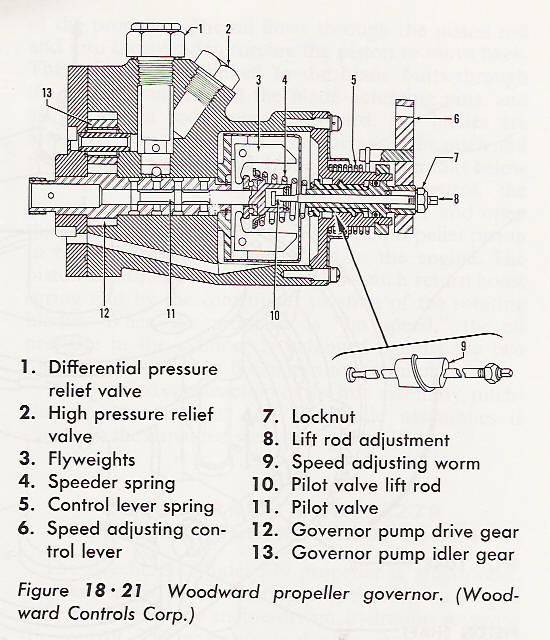
Governor Operation (Constant speed with counterweight ) the Governor supplies and controls the flow of oil to and from
the propeller. The engine driven governor receives oil from the engine lubricating system and boost its pressure to that
required to operate the pitch-changing mechanism. It consists essentially of :
1. A gear pump to increase the pressure of the engine oil to the pressure required for propeller operation.
2. A relief valve system which regulates the operating pressure in the governor.
3. A pilot valve actuated by flyweights which control the flow of oil through the governor
4. The speeder spring provides a mean by which the initial load on the pilot valve can be changed through the rack and
pulley arrangement which controlled by pilot.
The governor maintains the required balance between all three control forces by metering to, or drain from, the
inboard side of the propeller piston to maintain the propeller blade angle for constant speed operation.
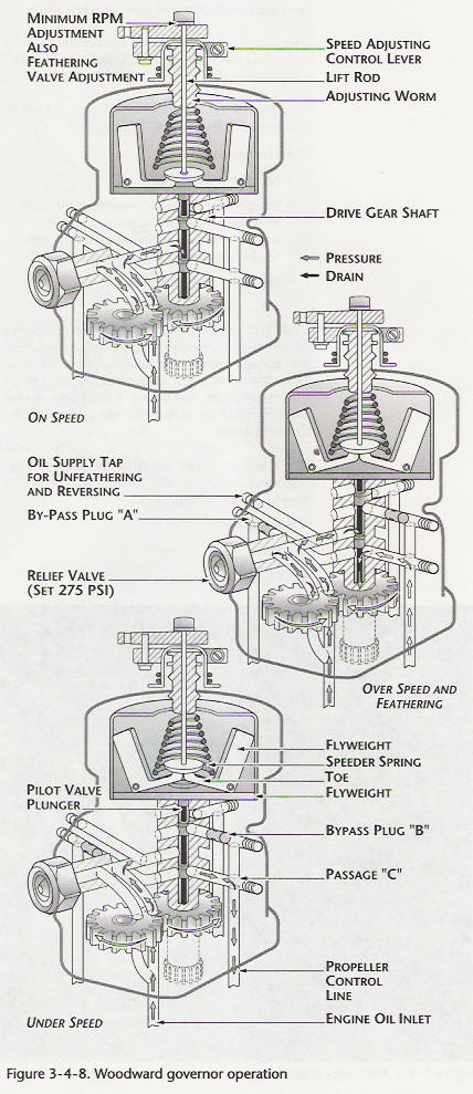
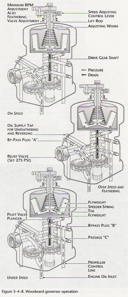
The governor operates by means of flyweights which control the position of a pilot valve. When the propeller r.p.m. is
below that for which the governor is set through the speeder spring by pilot , the governor flyweight move inward due to
less centrifugal force act on flyweight than compression of speeder spring. If the propeller r.p.m. is higher than
setting , the flyweight will move outward due to flyweight has more centrifugal force than compression of speeder spring
. During the flyweight moving inward or outward , the pilot valve will move and directs engine oil pressure to the
propeller cylinder through the engine propeller shaft.Principles of Operation (Constant Speed with Counterweight Propellers)
The changes in the blades angle of a typical constant speed with counterweight propellers are accomplished by the
action of two forces, one is hydraulic and the other is mechanical.
1. The cylinder is moved by oil flowing into it and opposed by centrifugal force of counterweight. This action moves
the counterweight and the blades to rotate toward the low angle positon.
2. When the oil allowed to drain from the cylinder , the centrifugal force of counterweights take effect and the
blades are turned toward the high angle position.
3. The constant speed control of the propeller is an engine driven governor of the flyweight type. Governor Operation
Condition
On-Speed Condition
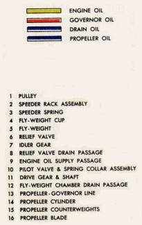
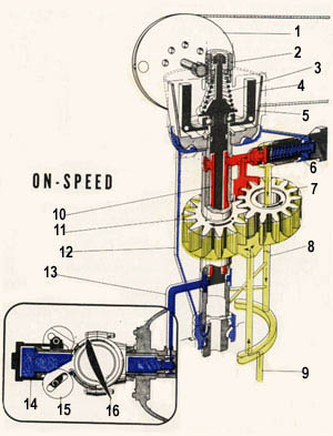
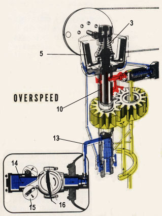
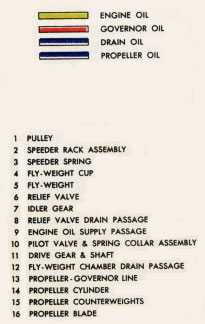
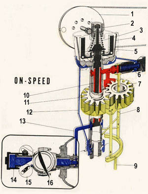
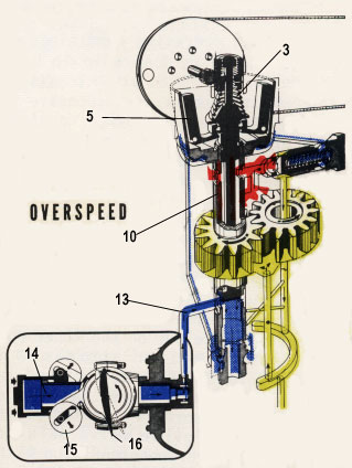
The on-speed condition exists when the propeller operation speed are constant . In this condition, the force of the
flyweight (5) at the governor just balances the speeder spring (3) force on the pilot valve (10) and shutoff completely
the line (13) connecting to the propeller , thus preventing the flow of oil to or from the propeller.
The pressure oil from the pump is relieved through the relief valve (6). Because the propeller counterweight (15) force
toward high pitch is balanced by the oil force from cylinder (14) is prevented from moving, and the propeller does not
chang pitch Under-Speed Condition
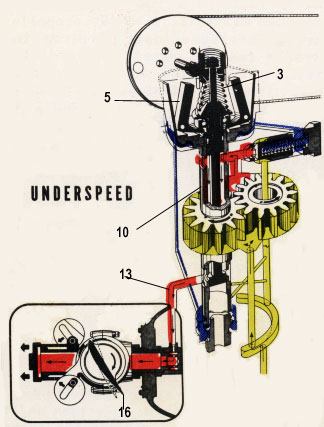
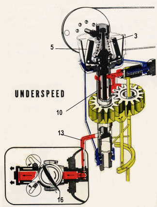
The under-speed condition is the result of change in engine r.p.m. or propeller r.p.m.which the r.p.m. is tend to
lower than setting or governor control movement toward a high r.p.m. Since the force of the flyweight (5) is less than
the speeder spring (3) force , the pilot valve (10) is forced down. Oil from the booster pump flows through the line
(13) to the propeller. This forces the cylinder (14) move outward , and the blades (16) turn to lower pitch, less power
is required to turn the propeller which inturn increase the engine r.p.m. As the speed is increased, the flyweight force
is increased also and becomes equal to the speeder spring force. The pilot valve is move up, and the governor resumes
its on-speed condition which keep the engine r.p.m. constant.Over-Speed Condition
The over-speed condition which occurs when the aircraft altitude change or engine power is increased or engine r.p.m.
is tend to increase and the governor control is moved towards a lower r.p.m. In this condition, the force of the
flyweight (5) overcomes the speeder spring (3) force and raise the pilot valve (10) open the propeller line (13) to
drain the oil from the cylinder (14). The counterweight (15) force in the propeller to turn the blades towards a higher
pitch. With a higher pitch, more power is required to turn the propeller which inturn slow down the engine r.p.m. As the
speed is reduced, the flyweight force is reduced also and becomes equal to the speeder spring force. The pilot valve is
lowered, and the governor resumes its on-speed condition which keep the engine r.p.m. constant.Flight Operation
This is just only guide line for understanding . The engine or aircraft manufacturers' operating manual should be
consulted for each particular aircrat.
Takeoff : Placing the governor control in the full forward position . This position is setting the propeller blades to
low pitch angle Engine r.p.m. will increase until it reaches the takeoff r.p.m. for which the governor has been set.
From this setting , the r.p.m. will be held constant by the governor, which means that full power is available during
takeoff and climb.
Cruising : Once the crusing r.p.m. has been set , it will be held constant by the governor. All changes in attitude of
the aircraft, altitude, and the engine power can be made without affecting the r.p.m. as long as the blades do not
contact the pitch limit stop.
Power Descent : As the airspeed increase during descent, the governor will move the propeller blades to a higher pitch
inorder to hold the r.p.m. at the desired value.
Approach and Landing : Set the governor to its maximum cruising r.p.m. position during approach. During landing, the
governor control should be set in the high r.p.m. position and this move the blades to full low pitch angle.
The Rotary Engine NewsLetter. Powered by Linux.
ACRE NL web site.
http://www.rotaryeng.net
Youtube key word UTUBPLEASE
Copyright 1998-2008 All world wide rights reserved.