It is sometimes difficult to mount fuel pumps in AC wings.
Most people don't do it. They mount the pumps on the firewall.
Paul Lamar
Paul,
I'm just starting construction of my fuel tanks for a Zenith CH-640.
I'm opting for a four wing tank system. I'll likely be using a 16b
conversion,
fuel injection based on your designs. With the discussion on-going about
in tank fuel pumps and fuel return lines, I am asking if I need to make
accomodation for anything special. Presently, my tanks have no provision
for
a fuel return or in tank pump. Would it be necessary to design in any of
this
stuff?
Thanks, C. Smith
Yes you might think of adding a large removable panel in the root
ribs for internal pumps. The 640 has a nice thick wing for internal
pumps. Looks like the tanks are in the leading edge. If not
practical use two lines from each tank. One for feed according
to the plans and one for return fuel.
Paul Lamar
Correction, I meant 13b engine.
C. Smith--
So the EFI system with a fuel return line would preclude the use of a
fuel flow meter to keep track of fuel used and burn, unless someone
knows of a meter that subtracts the return flow?
so with a 4 tank system, thats 8 fuel lines, and a tank selector valve
ganged 4x4? 4 separate fuel pumps, and control wiring?
No other way to do this? I'm bummin' out.
C Smith
Unfortunately that is one of the drawbacks of a fuel return system.
With the 555 system all injector pulses rates and widths are the
same so one can build a simple flow meter that consists of diode
and large capacitor that will sum the pulse width and rate from
one injector. That sum can be read by a digital voltmeter to give
you a flow rate. It is calibrated with a pot so it can read
out GPH to the nearest .01 gallon. Very simple. Computers systems
do it the same way except they do it in software.
I might build the diode, capacitor and pot into one of the PC
boards. You have your choice of read outs. One can probably test
the scheme on a car EFI system.
Paul Lamar
Just a quick reminder (in case anyone forgot) that the rising-rate
vacuum-referenced fuel pressure regulators are intended to be 1:1 and
increase fuel pressure 1psi for every 1psi manifold pressure increase
to keep a
*constant differential pressure*.
By design the differential pressure across the injector should be
constant at all times, irrespective of manifold vacuum or boost.
Ratios other than 1:1 exist, but those are generally for radical
supplemental fuel pressure regulators used when applying forced
induction without any other means of fuel enrichment. With rates like
7:1, these are a fairly bad idea.
In other words, there is no necessary modification to a 3D fuel table
to take this action into account. The injectors can be assumed to
operate linearly (neglecting opening/closing time effects). Even if
the differential pressure was changing, there is no need to have a
separate fuel table and pressure sensor, as this information will be
incorporated into the 3D map when the engine is tuned.
Paul: Regarding flow measurement from injector pulsewidth, remember to
consider injector dead time (opening/closing) which becomes very
significant at low duty cycle or high RPM. Different injectors have
different properties in this department, which vary with applied
voltage.
-Chris
No computer. No 3D maps. The load on an aircraft engine never varies
with fixed pitch prop load. It is a much simpler system than a car
engine.
If we don't use a rising rate regulator the engine might be too rich
on the bottom end. I am just using it to supplement the linear mass air
flow sensor voltage controlled TLC 555. Just another way of tailoring
the curve. It may not be necessary.
I have a scope hooked up to monitor the dead times.
Paul Lamar
Paul,
the reason we use manifold pressure to tweek the fuel pressure even on
production cars is to keep an even pressure differential across the
injector. on boosted applications, this is even more important.
The simple cure to all these controls is to pwm the pump. It takes 2
sensors, one on the fuel line, and one to monitor manifold pressure.
The one
on the manifold pressure can be quite accurate even with all the pulsing.
all that is required is a long length of 1/8" od thick wall plastic
tubing.
the friction of moving the air through the long length of tiny tubing
provides the damper to smooth out the signal.
We have a pwm module we already use for controlling dual electric fans
based
on engine temperature. it may be simple for us to modify it to control
fuel
pumps instead.
If you are interested, I will find out what the production sensors
ford uses
on returnless systems and work on adapting them. We can drive any external
pumps with this as well as any of the submerged pumps.
Aeromotive already sells a pwm drive module, I just don't like the price.
Check out the pump the jegs is selling. I like the fact that you can
use an
fittings.
http://www.jegs.com/p/JEGS/1167179/10002/-1
Larry
Not interested right at the moment as I want to keep this system as simple
and cheap as possible with a lot of history. Also it is a risk as it is
designed for cars and the PWM pump system may not be up to aircraft high
duty cycles. Down the road may be OK.
BTW I have upgraded the write up on the web site so check it out.
http://www.rotaryeng.net/simple-cheap-555.html
Paul Lamar
Just caught up on this thread & noticed the comment on:
"So the EFI system with a fuel return line would preclude the use of a
fuel flow meter to keep track of fuel used and burn, unless someone
knows of a meter that subtracts the return flow?"
This product does exactly that:
http://www.matronics.com/fuelchec/RFC/index.htm
Dynon might have one too, I recall something in their installation guide
about this topic.
--Kenny A.
I appreciate the information everyone has contributed. The Matronics device
does do the math, but it appears it does nothing else but produce a pulse
train that must be processed by another device, why is it called a controller
when it controls nothing, it is a flow totalizer. The price is kinda high too,
about 1/3 the price of a used 13b.
What I'm looking for would provide the data in a format acceptable to an EFIS
like a Garmin G-600. I'm wading through the data on the Dynon site.
Thanks for the information.
I am not trying to be critical of the system Paul is engineering, he
has specific design goals. I was just hoping for another option. The
Fuel injected Cessnas I've had, didn't use a fuel return and simple fuel
flow sensors were easily installed and interfaced with the GPS.
In the end, I could probably
engineer a device to do what I need.
I think I'll have to hold off on the tanks until Paul has finalized
the system, and I have a better understanding of the fuel system
requirements for the rotary engine. I can easily add an extra fitting
to the tank, but in tank pumps has got me worried. Does the pump fit
in the top, bottom or side? the skins are .025 (already purchased the
material) I don't know if that is suitable to support the pump.
Rough tank dimension is 32.6"x18.5"x9". Changing the material for the
side bulkheads is doable.
Sorry to bore the group with my questions, but I'm not an engine
expert and I want to get it right.
C. Smith
In my 555 system there is no need to have the pumps in the tank
if you have pumps that have fittings on the intake side (MSD
and others).
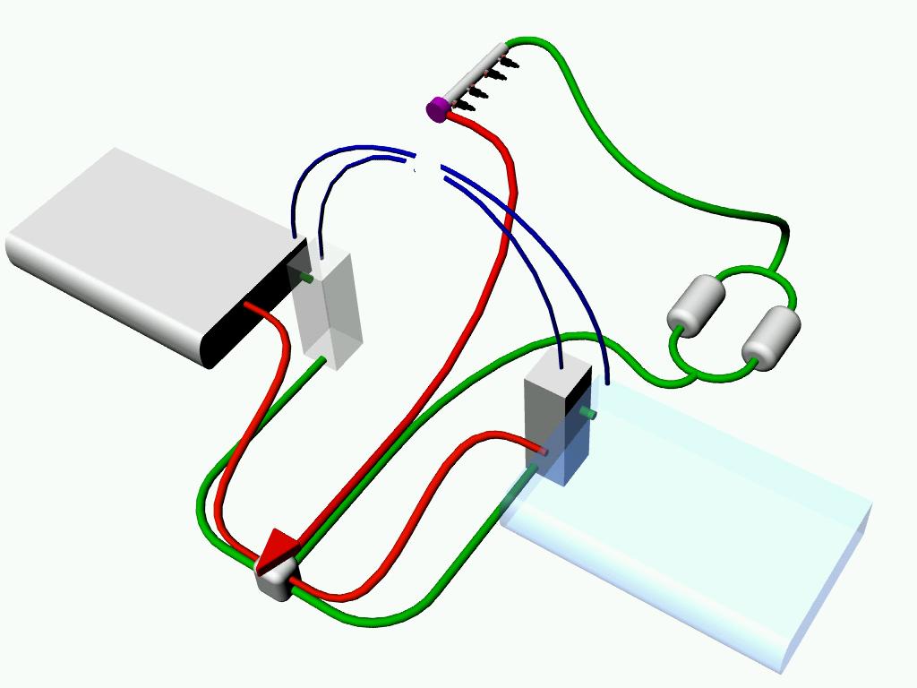
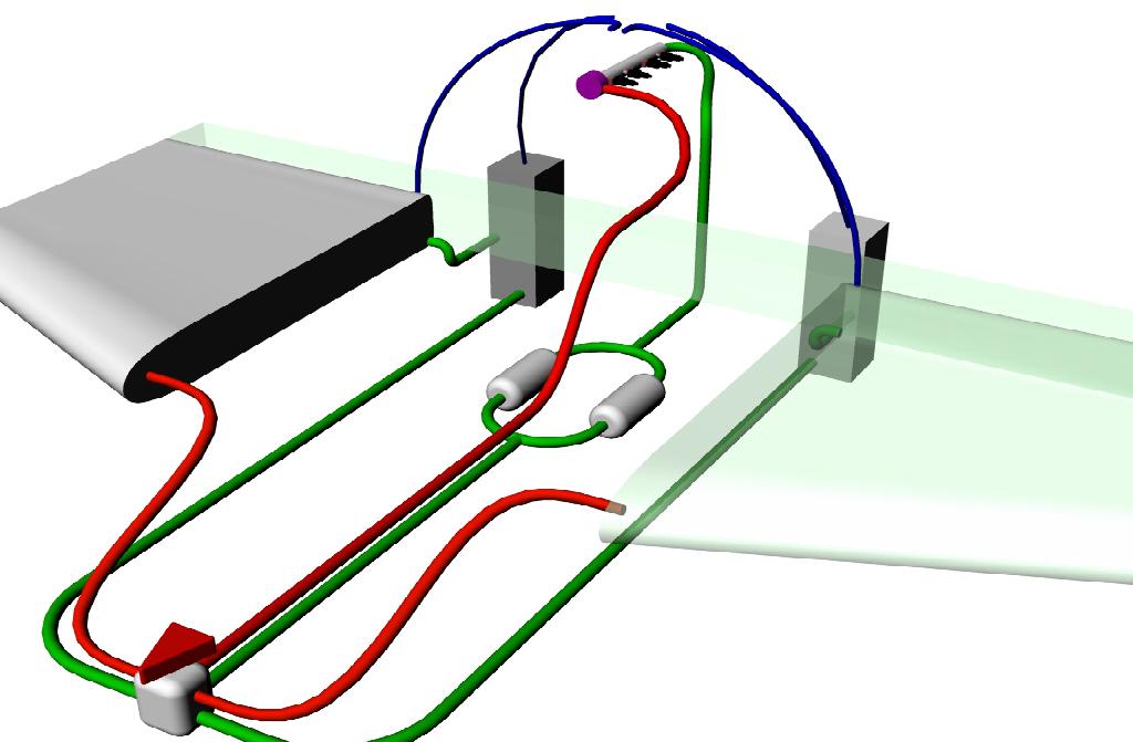
Here are a few plumbing suggestions for return systems.
Paul Lamar
--
The Rotary Engine NewsLetter. Powered by Linux.
ACRE NL web site.
http://www.rotaryeng.net
Youtube key word UTUBPLEASE
Copyright 1998-2008 All world wide rights reserved.