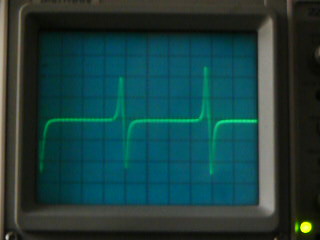
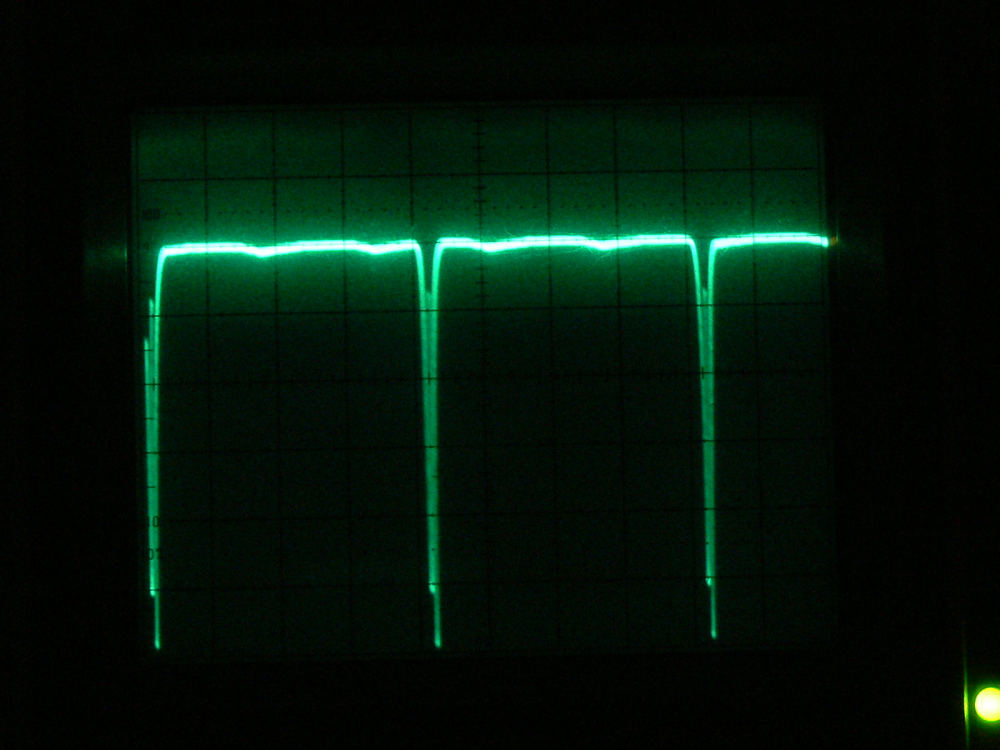
I got it down to about 50 RPM or so using the new ABS
sensor to trigger the 555 fuel injector. It took a couple
of diodes and a resistor. Next change will be to check
the fuel flow meter circuit. Then I will do another batch
of PC boards for further testing
Here is the latest version. A few more minor changes on the way.
When Larry gets the new slide throttle done we will go back
on the dyno with the RX8 p-port engine and this 555 EFI system.
I have a good slide throttle I can use so no rush on Larry's.
Things are not going as fast as I like as I am spending mornings
installing a new central heating system in our house.
Paul Lamar
Radiant, or forced air?
Matt-
Forced air. The attic is only a foot and a half high at the highest :)
I had to build a dog house on the roof to get the furnace up
there.
Paul Lamar
California architecture... :)
Matt-
You got it. Never in the history of man has the price of houses
been so high for so little :)
Paul Lamar
Hi Paul
That 555 gets better all the time.
I trying to emulate your circuit on CircuitWizard, the nearest components
included in the software don't cross reference very well. And I am not very
component savy either, so that a bit of a handy cap.
I have substituted an IRF540 for the power fet it seemed the closest and as
I have Bosch EV6 injectors, they seem to need less power, to drive anyway, a
comso drill pwm Maplin catalogue no.RN31U will drive one of these but not
the EV1, and can be ramped up on the pressure if needes.
In the simulation I am using a 12v relay.
A function generator set at +/- 18v 60 Hz, in place of the E- shaft trigger.
Digital voltmeters for the Fuel Flow and also added another to monitor the
MAF voltage the LM358 seems ok.
C1 R1 and 1N2004, and the extra diode on the trigger and the other capacitor
values would be a great help, when I run the simulation I get a lot of on
screen components blowing mostly the these ones.
House prices are terrible here too.
Clive C
What is the resistance of the Bosch injector. It should be around 10 ohms
to work in this circuit.
C1 is .1 ufd
and R1 is 10K
What is the pulse width of the function generator? It should be less than
1 msec. Also keep the voltage down to less than 15 volts as 18 might
blow the TLC 555.
Paul Lamar
Hi Paul
Thanks, I was using the sine wave +9-9 total of 18volts.
The function generator is basic but if I set it to 80% duty cycle the scope
pattern looks similar to what you have, when it measured at pin 2, just cuts
off the + and keeps the negative part. I have only had the program week and
think I'm going approx the general vicinity of the right direction.
Will play with it will come back when I've made some progress.
The Bosch EV6 is 14.8 ohms do you think this would be too much?
Clive C in the UK
No that is fine for the injector resistance. Early peak and hold injectors
had about 1 ohm so initial current was 10 amps or so.
Those have pretty much disappeared.
I think the output impedance of the function generator may have something
to do with it. I used an actual ABS sensor set up on the bench.
The higher the RPM the higher the voltage from the ABS sensor so I was worried
it might kill the 555 so I put the conditioning circuit in there with a pull up
resister. It seemed to help at lower RPM.
I am not that far ahead of you.
Let me know if you need any help.
Paul Lamar
--
The Rotary Engine NewsLetter. Powered by Linux.
ACRE NL web site.
http://www.rotaryeng.net
Youtube key word UTUBPLEASE
Copyright 1998-2008 All world wide rights reserved.