Hello Paul-
Sent this to Tracy earlier today; thought I would pass it along in case
someone on the list has seen this before...
Had some peculiar behaviors in that latest tuning attempts. Hopefully
you'll have some suggestions.
Background-
- 13b, p-ported, with slide throttle design & "tuned" intakes
- LS1 injectors
- EC2 with latest p-port firmware
- EM2
- 6800 field altitude
- 55F OAT
- Known to be under propped (has a 72x72 160hp 2-bladed prop. Needs a
72x109 230hp 3-bladed prop)
Symptoms-
If we run the engine with the manifold pressure lines DISCONNECTED
from
the EC2:
- Engine starts very easily
- The engine runs quite smoothly across a pretty wide rpm band after
tweaking the manual mixture control.
- Reasonably smooth running as low as 1500rpm engine (526rpm prop!)
- Very smooth running 3000 - 4800 RPM.
- Above 4800 rpm we seem to "run out of enrichen" on the manual mixture
control & the engine stops.
- MAP table view on the EM2 real-time shows the EC2 using map location
59
or 91 (MP constant matching atmospheric pressure) depending on high/low
throttle (as expected)
If we run the engine with the manifold pressure lines CONNECTED to the
EC2:
- Engine noticeably harder to start
- Engine will not run smoothly at any rpm
- Significant surging pattern -- rpm increases rapidly, followed by
engine stumble to low idle rpm, followed by next surge.
- Engine often stops during the stumble / hard to restart
- MP pressure varies rapidly based on engine rpm
- Significant manual mixture changes can help ease the surges somewhat,
but never enough to get the engine to smooth out enough to let us see
if MAP
values could be tweaked.
Looking at the MAP table with engine off, it seems like all map cells
are
at
0 -- as expected. I did not check all 127 cells, only the top cells
(say
100 - 127).
Mark (Rocky Mtn High)
That is good evidence the 555 system will work fine :)
We noticed this phenomena on the dyno test of your engine.
I am not privy to Tracy source code but the last time I talked to him
about it was a couple of years ago and he was taking only one sample
of the intake manifold pressure per e-shaft revolution.
Using a computer this takes only about 10 usec.
http://en.wikipedia.org/wiki/Microsecond
Light travels only one mile in FIVE microseconds.
That is 10 millionths of a second. 100 usec is one msec or one
thousands
of a second. This is a very brief period of time so the manifold
pressure
is jumping around a lot in a p-port tuned manifold. It could be
anything
or even above atmospheric pressure at some times. That is what p-port
tuned
manifolds do. See the enclosed chart. A lot depends on WHEN you sample
the pressure. It changes with RPM in unpredictable and mysterious ways.
IMHO this is confusing the heck out of Tracy's computer. IMHO you need
to feed the manifold pressure from both intake tubes past the slide
throttle
using very small hoses into a beer can and then tap out of the beer can
with
one normal size hose going to the pressure sensor in the computer.
Hopefully
this will damp the pulsations and average the intake manifold pressure.
Al Gietzen tried this as I recall and it did not seem
to change anything. I don't know what size hose Al used
but I think very small hose is essential. On the order of .030
inside diameter or smaller.
Paul Lamar
Mark,
You don't need the beer can. If you use 1/8 od tubing, make a coil of
tubing
using at least 20 feet of tubing. 30 feet may be better. The length of
tubing works to damp the intake signal to something that the computer
makes
sense with. My experience is the tubing can work better than a
reservoir
as
it is using the friction of air molecules on the surface of the
tubing as
the damper, and will respond faster than a reservoir, but still be
damped.
That doesn't mean the maps are correct, as it sounds like the manifold
pressure side of the map is way off.
To trouble shoot being rich or lean, have a squirt bottle of fuel handy
and
give the runners a quick squirt as the rpms are declining (while
surging).
If this makes them instantly recover, the system is going lean. if it
forces
it to die, the system is going rich. that will tell you which way to
go in
the tuning. My guess is it is very lean with the sensor connected. The
sensor disconnected simulates wide open throttle with no manifold
vaccum
with high fuel demand, so the ecu increases the pulse width to the
injectors. When the sensor is connected, and the ecu sees manifold
pressue
decreased, it reduces the pulse width.
make sure you are careful when performing this test...... and of course
you
have a fire bottle handy...
hope this helps,
Larry
Hi Larry,
20 feet of tubing is a fair size expense and bundle.
My lathe tail stock chuck will not hold a tiny .030 dia. drill or I
would
make some orifice up and send them to Mark.
Perhaps you could make up some orifice that will plug into
red silicone vacuum plumbing tubing. OD of the orifice would be .125 to
fit
the tubing. 0.030, .025 and .020 ought to cover it.
The rest of the world uses mass air flow sensors for a good reason :)
Paul Lamar
Paul,
If you need a .03 orifice I would suggest going to local motorcycle
aftermarket
shop and checking their selection of carburetor pilot jets. If I recall
correctly I'd check a Kehin size 20 or 25 pilot jet. That should be
around
.030 inches.
Bill Jepson
Good idea bill.
Carb jets would be a gold mine of tiny orifices.
Paul Lamar
Paul,
the small needle valves sold at hardware stores for use on small tubing
would give you an adjustable orfice for developement work.
Larry
Another great idea. Are you listening Mark?
Paul Lamar
You might also consider using the (unused) oil injector holes - I can't
remember what size they are.
That area might provide a slightly less erratic MAP source.
Plus you may be able to get a true VE-Volumetric Efficiency number.The
measure value would need to reduced (based
on calculations) to compensate for compression in the chamber.
Cheers
Cary
Depends on when you do it. Since the computer does it in 10 usec
it is only a point in time.
Here is a question for everybody. Assuming you can only sample
the intake manifold pressure once per revolution of the e-shaft where on
this curve would you choose? I chose to do it 135 degrees after
top dead center. The red X marks the spot. Of course the shape of the
curve changes drastically with RPM because the intake is tuned for
only a narrow range of RPMs.
Paul Lamar
Paul,
Same place for me. I want to sample the MAP after the intake port opens
but before the injectors spray fuel.
I orginally wanted to sample at the oil injection hole like Cary
mentioned but since my injectors are now directly in housing in that
area, I run the risk of fuel entering the hoses.I have decided to
sample upstream of the fuel injection but downstream of the slide
throttle.
As an aside, perhaps injecting so far out on the manifold is causing
erratic readings for Mark's Map sensor.Here is what we know. It runs
fine at idle and mid rpms without any computer control, besides the
lean- richen control. This is very carb like and you have the
identical experience of not being able to run the engine at low rpms
until you switched to carbs.
The injection of fuel changes the density and temp. of the air mass
before it reaches the sensor at which time the computer tries to
compensate by adding even more fuel?
Sort of like injecting chlorine into the pool plumbing system before the
pump sensor.
Doug in Japan
Your spot like my spot won't work. Our samples are meaningless. The
curves moves away at all other RPMs. That specific curve is only good
for one
RPM and perhaps only one throttle opening. I get a feeling that people
are not getting this.
Paul Lamar
We are guessing. Sampling may or may not be meaningless.
Without knowing more about Tracy's system, we have no idea how often it
samples MAP and if/how it is averaged.
The same goes for many other factors.
Cheers
Cary
He told me he only samples once per rev. He can not get an average
by sampling once per rev. It takes about 10 usec or less to read the
pressure sensor.
BTW We will never know more about his system as the source code, unlike
the Megasquirt source code, is proprietary. On the other hand I would
rather
be beaten with a 2 by 4 than learn "C" :) If I were doing a EFI
computer I would
do it in assembly language (which I already know) and publish the
source code.
http://www.rotaryeng.net/RT1.pdf
http://www.rotaryeng.net/skid-pad-C&D.pdf
---------------------------------------------------
I have started to enhance the Megasquirt software flow chart to
understand
how it handles manifold pressure measurements.
Would you like to contribute Cary?
Paul Lamar
Hi Paul;
Thanks for the confirmation on Tracy's MAP sensor sampling.
What did you have in mind and what Megasquirt code branch are you
looking at? There are assembler and "C" versions depending on the
hardware.
IIRC, people have had Pport tuning issues with the Megasquirt as well.
We can arrange for the 2 by 4 (well, a 1.5 x 3.5 anyways :)
Cheers
Cary
I am looking at the assembler as it is easy to associate a piece
of code with what it actually does. I don't know C anyway. The earlier
Megasquirt is probably better suited to aircraft adaptation anyway.
Basically I want to find the correlations if any with what
Tracy is doing to better help people tune Tracy's system
when applied to a p-port.
Paul Lamar
There has been discussion on here about problems that resonant airflow
reversion might cause - even with a mass airflow sensor (MAF). It occurs to
me that if the sensor is located on the cold side of the plenum used to
contain the reversion fuel cloud, much/all of the reversion seen by the MAF
would be eliminated. The MAF would still see pulsing flow, but probably no
reversion. The plenum needs to have adequate volume.
Regards,
Matt-
I agree.
That is where I advocate locating the mass airflow sensor.
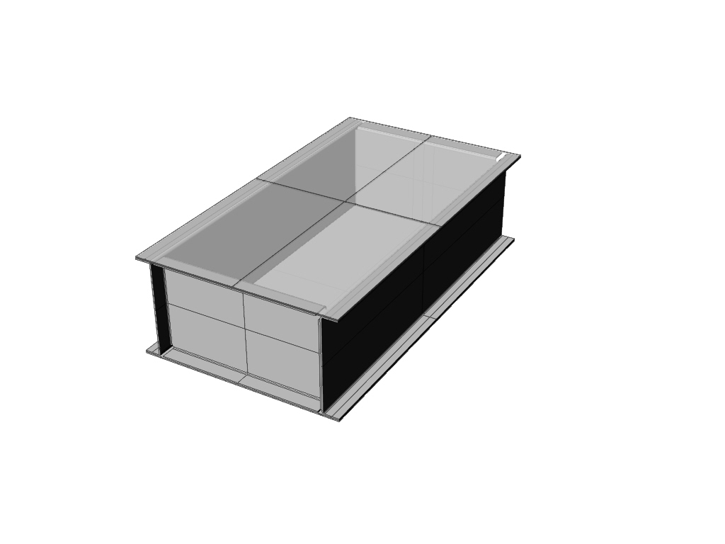
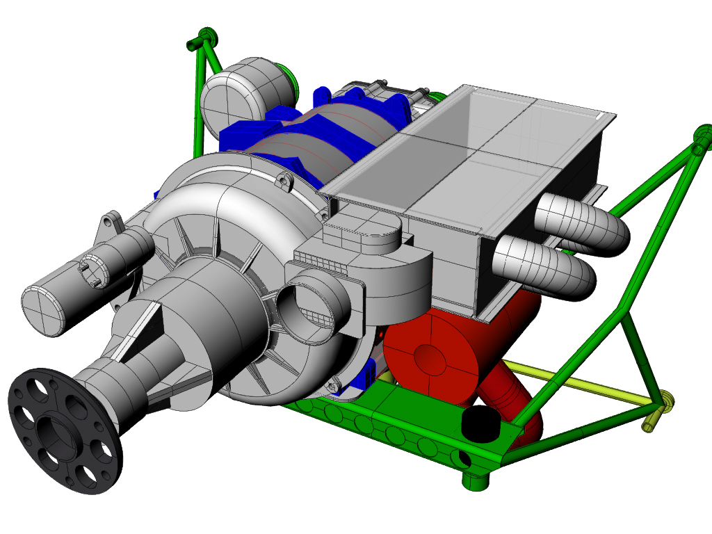
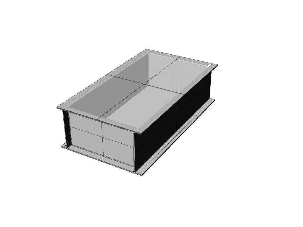
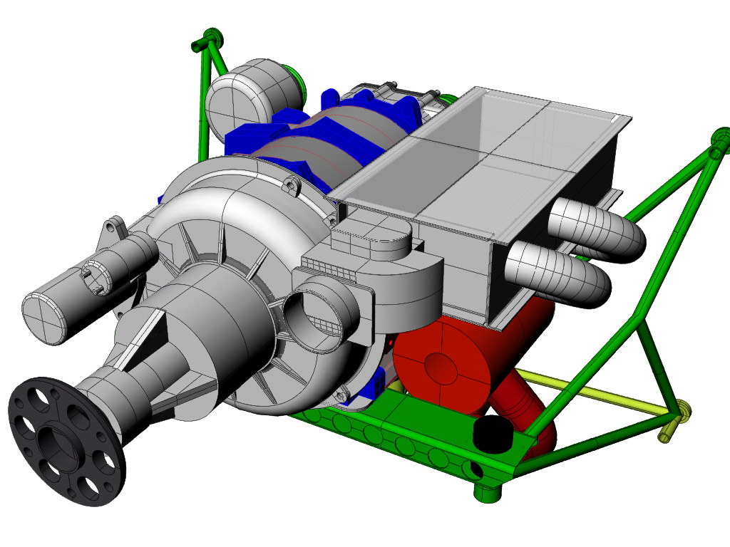
Here is an earlier 3D on the subject. This is a 2nd gen mass
airflow sensor.
Paul Lamar
--
The Rotary Engine NewsLetter. Powered by Linux.
ACRE NL web site.
http://www.rotaryeng.net
Youtube key word UTUBPLEASE
Copyright 1998-2008 All world wide rights reserved.