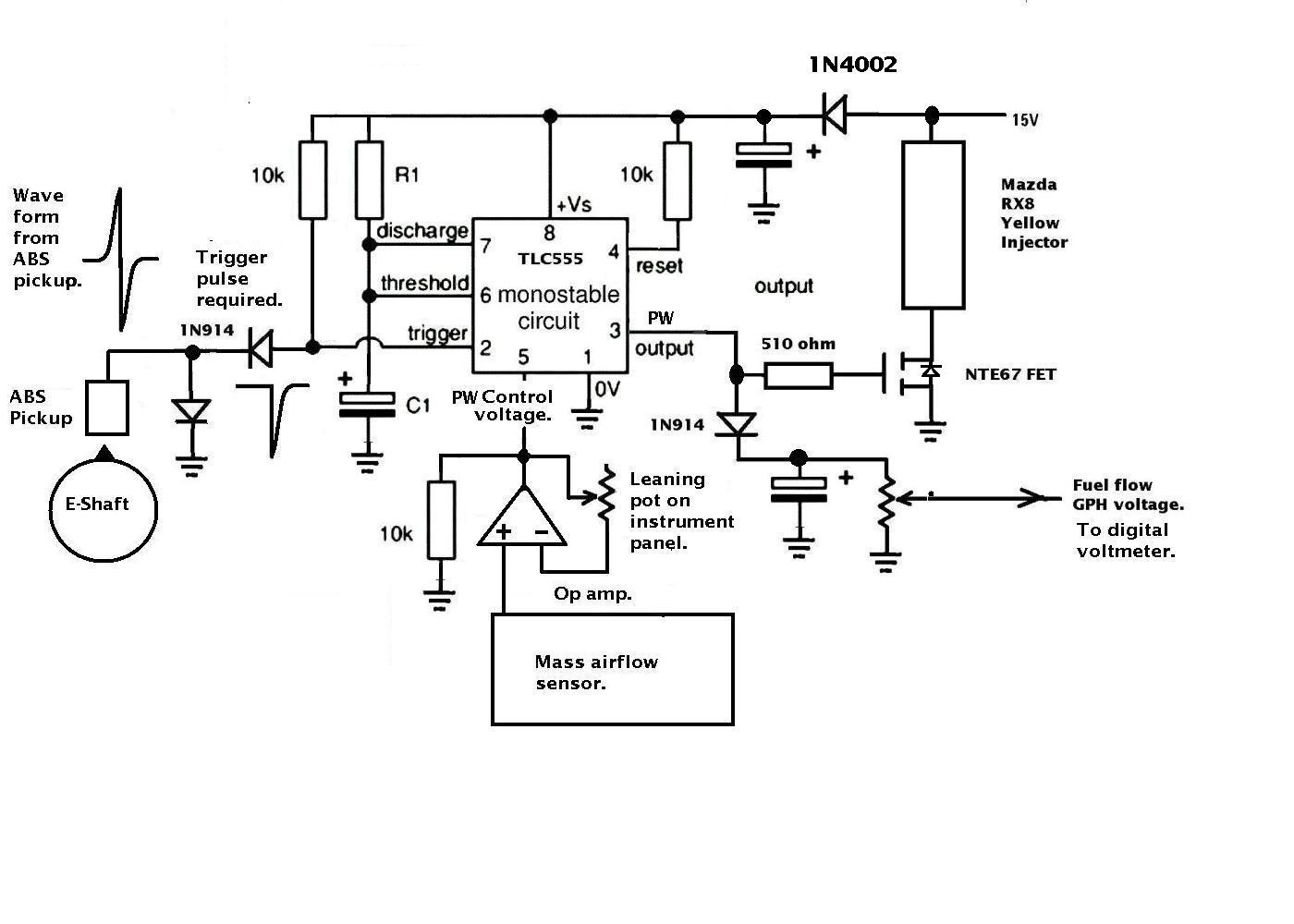
Schematic as drawn has several errors:
1) 1N2004 should be 1N4002 ??
2) Gain control on Op-Amp between Mass Airflow Sensor is miss drawn.
Pot does nothing, gain of circuit is fixed at +1.
3) Output for GPH gauge needs to be an integrator, not a peak detector.
You want measure the "average of the on time" to get GPH.
4) There has to be some sort of snubber circuit across the injector coil,
otherwise the turn off voltage spike will destroy the FET.
JCP
--- On Wed, 4/8/09, Rotary Engine
<rotaryeng@earthlink.net> wrote:
From: Rotary Engine
<rotaryeng@earthlink.net>
Subject: FI Control
To: "AAA Put this in the To box"
<rotaryeng@earthlink.net>
Date: Wednesday, April 8, 2009, 10:09 PM
I went to some of the RX 7 groups online to find out the best way to control
FI. I am looking at Megasquirt as a plan B or C if the 555 analog system does
not work out. I guess there is manifold pressure which is not stable on a P
Port. Ther is Mass air flow which is being proposed for the 555 system and is
supported by Megasquirt. The RX 7 guys seem to think the MAF sensor could
impead the air flow to make big horse power. 200 to 250 HP does not seem to be
big HP when they are getting a lot more out by turning the engine faster. How
does TPS or throttle position sensor fit into this? Thanks for any help
Joe Berki
Limo EZ 13b P Port
As long as the mass airflow sensor is around 5.5 square inches it should be
fine.
That is something about 2.625 or 2.75 inches in diameter will give around
250 HP. The throttle position sensor will not work with the 555 system
not is it needed.
--Paul
Paul
How would the mass flow sensor work with a turbo charger on the front
end? I Think that the MAF sensor would be calibrated for ambient
pressure N/A applications.
Doug in Japan
The 555 system has a provision for scaling the airflow signal.
The gain of the op amp can be adjusted.
It responds to mass flow only and not pressure per se.
Paul Lamar
Schematic as drawn has several errors:
1) 1N2004 should be 1N4002 ??
2) Gain control on Op-Amp between Mass Airflow Sensor is miss drawn.
Pot does nothing, gain of circuit is fixed at +1.
3) Output for GPH gauge needs to be an integrator, not a peak detector.
You want measure the "average of the on time" to get GPH.
4) There has to be some sort of snubber circuit across the injector coil,
otherwise the turn off voltage spike will destroy the FET.
JCP
Thanks John. Do you have a suggestion for fixing the op amp circuit?
If you don't mind use ms paint to draw in the proper resistors. I think the 10K
resistor is mis drawn to the output pin instead of the input pin.
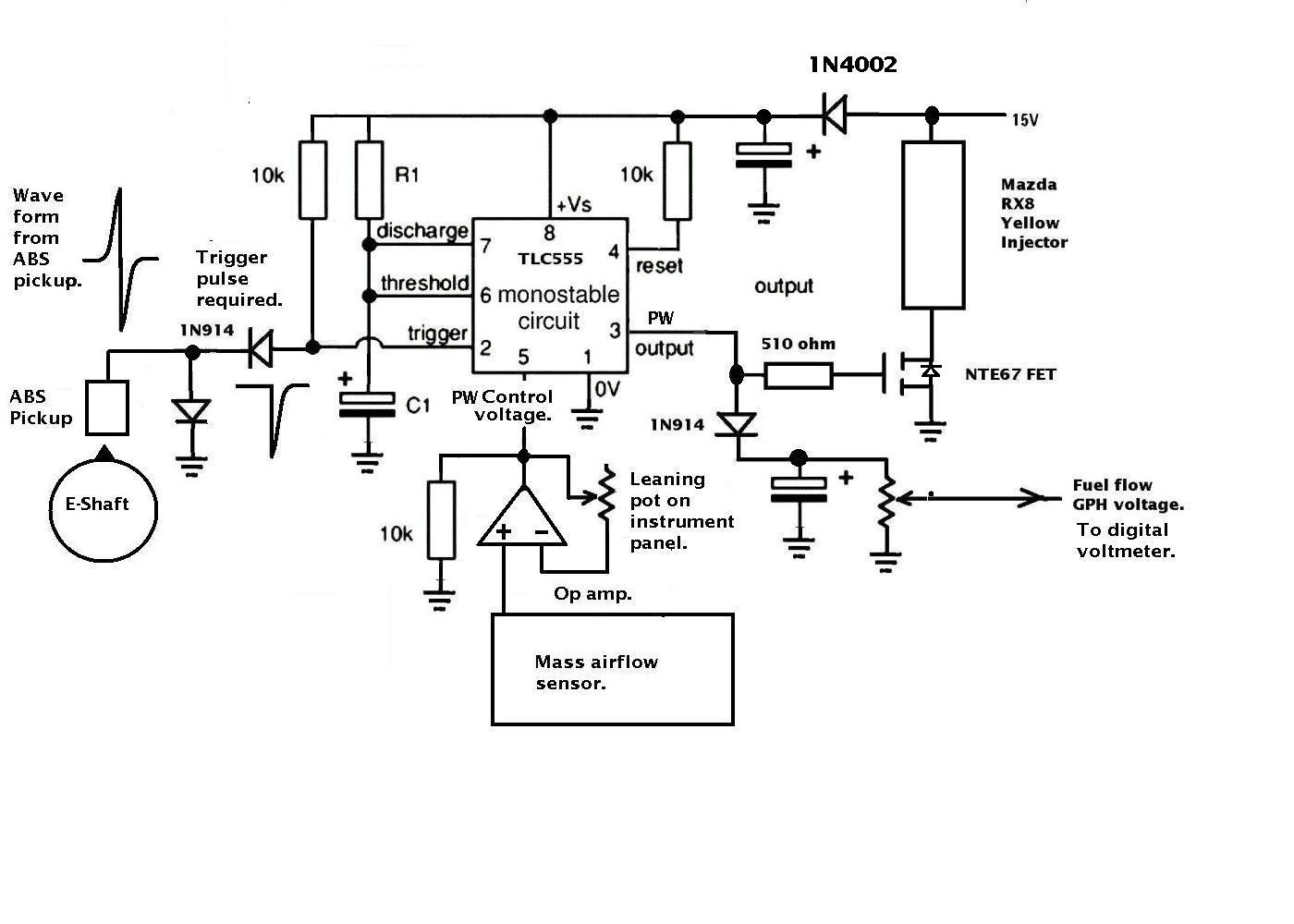
I also think the snubber is built into the FET. I just failed to draw in
the diode. At least I have not failed one yet. I added it to the schematic.
I forget to fix the 1N4001 diode number as that came up already.
Here is the schematic again with the diode and the snubber fixed.
Paul Lamar
--
The Rotary Engine NewsLetter. Powered by Linux.
ACRE NL web site.
http://www.rotaryeng.net
Youtube key word UTUBPLEASE
Copyright 1998-2008 All world wide rights reserved.