This wireless torque sensor technology could be applied to a short
small diameter shaft extending out of the intake side of a turbo charger.
The end of the shaft would have a small adjustable pitch propeller capable
of 100,000 RPM to act as an adjustable load. The torque sensor is wireless
so nothing else is necessary. No need to make a reduction gear box yet.
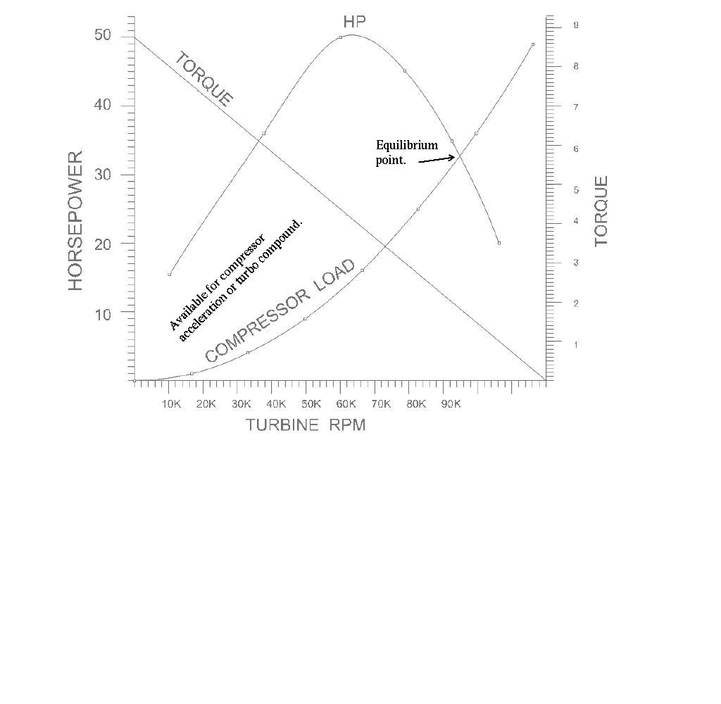
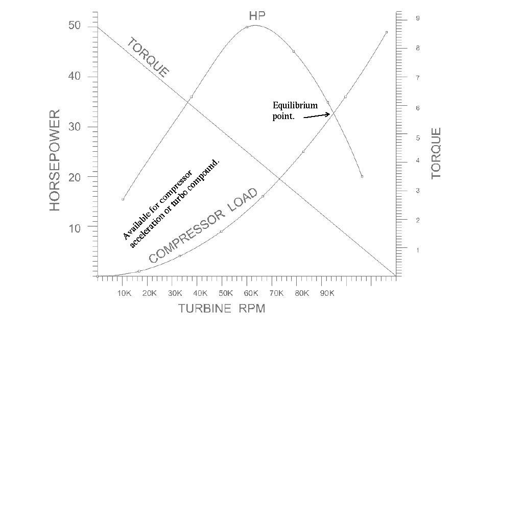
This first step is to demonstrate the amount of excess HP
from the turbo charger turbine. Any automotive turbo charger
will work and it is then possible to evaluate different turbine
configurations for aircraft use optimization purposes.
If the torque on the shaft is two foot pounds at 100,000 RPM the HP is
2 X 100,000/5252 or 38 HP. Feeding the turbine power back into the output
shaft for a 200 HP base engine the power would jump to 238 HP with the
same fuel burn. The rotary engine BSFC would then be .46 times
200/238 or .386 which is a very significant reduction in fuel burn
only possible in true diesel engines.
----------------------------------------------------
I was driving to the airport tonight to pick up Robin
and had a better idea on how to measure the HP output of
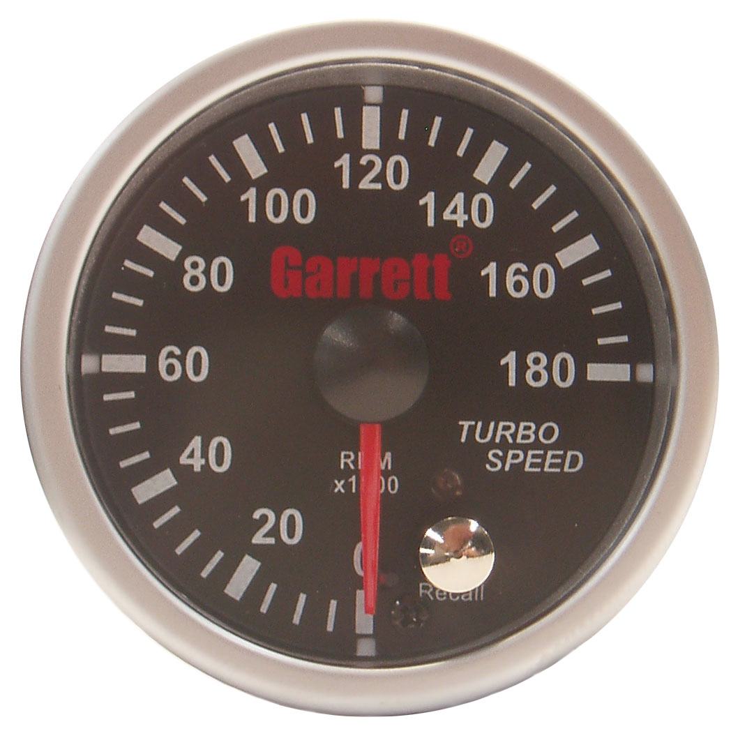
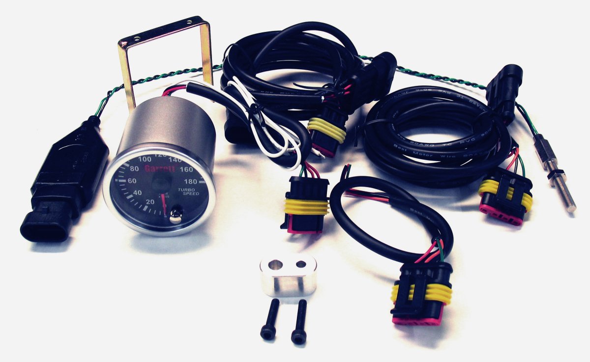
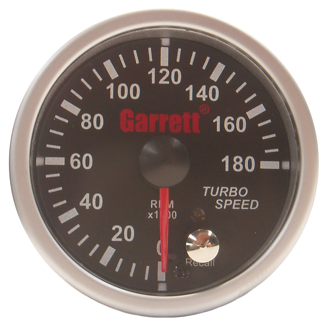
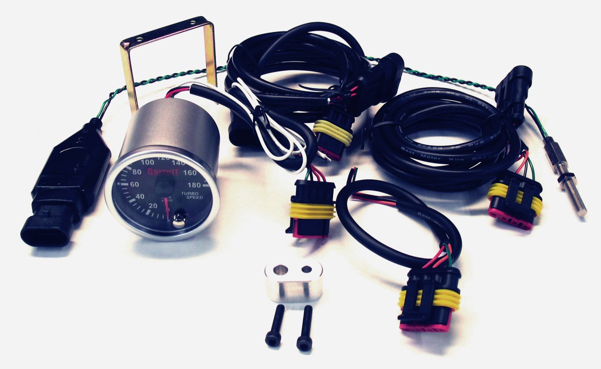
a turbo charger turbine. You will need a turbocharger tach anyway
so get the Garrett turbo charger tach kit. You will then need an oscilloscope
to measure the twist in the steel shaft coming out of the front of
the turbo charger going to the load. My guess is the shaft diameter
could be as low as 3 mm. The optimum diameter can be calculated.
If you know when the turbo tach is sensing
a compressor blade and when the prop load blade passes a point than
we can measure the shaft twist directly. You calibrate the system
with a small torque wrench that reads out in inch pounds as you twist
the shaft statically.
For an example; the turbo
is reving at 100,000 RPM or 1,666 revs per second it takes
.0006 seconds or 600 micro seconds to make one rev. The prop blade
can sync the scope with a photo cell or hall effect sensor and the time
it takes in microseconds to see the next compressor blade is the
twist or torque in the shaft.
My scope works down to .1 usec (microsecond) per division.
So one can resolve time down to .01 microsecond or one tenth
of a division. A TO4 turbo charger has 7 compressor blades so that is about
one blade per 86 micro seconds. Good enough. Twice as good at 50,000 RPM.
In effect this is a low cost turbo charger turbine dyno.
Model airplane propellers are ideal cheap loads as when the tips
go supersonic the turbo charger turbine runs into a torque brick wall.
Change the model prop diameter to change the RPM where this happens.
The turbine should put out max HP somewhere around 50,000 RPM.
Use ear protection as this will be noisy! Just like the rotary
exhaust noise is the sound of waste HP!
-----------------------------------------------------
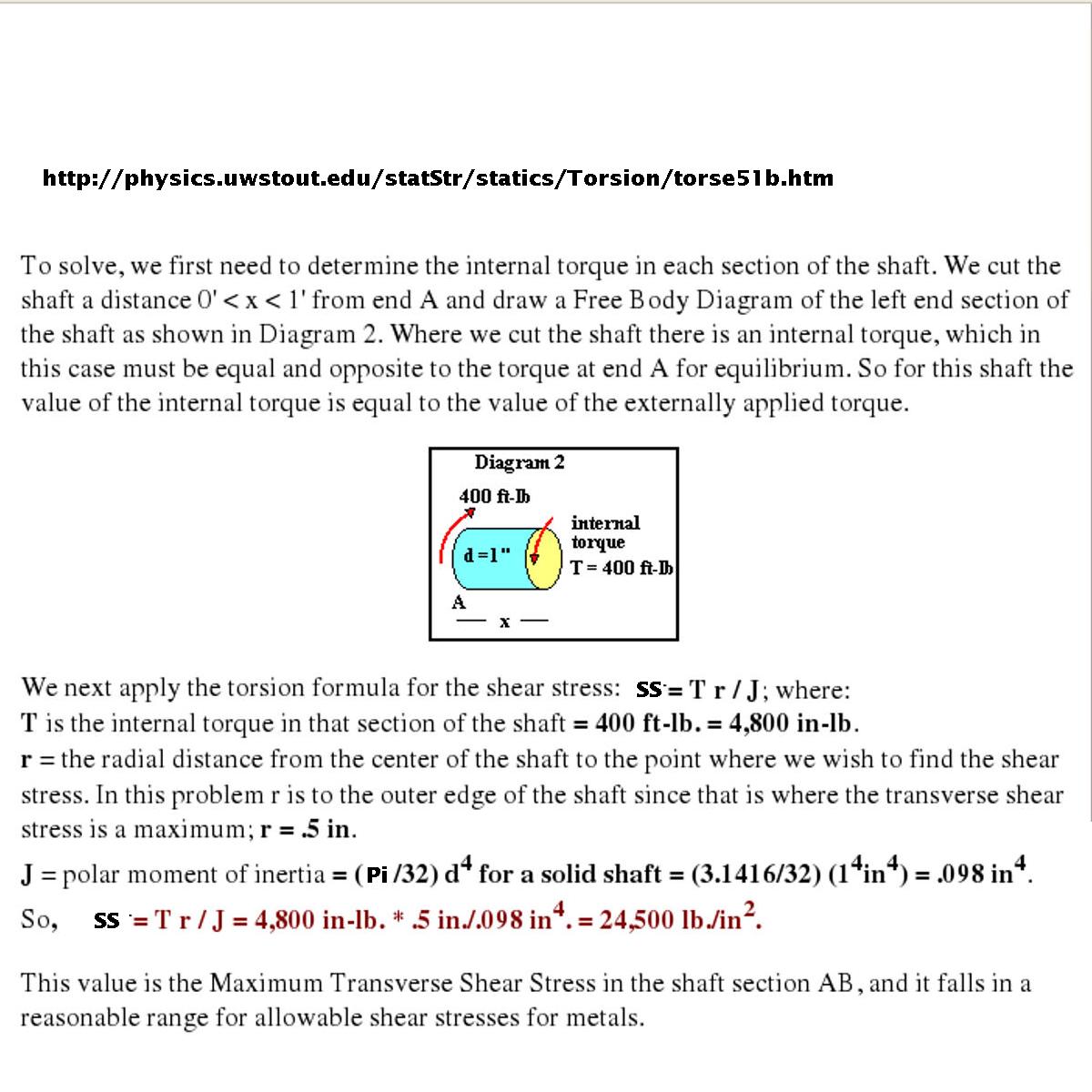
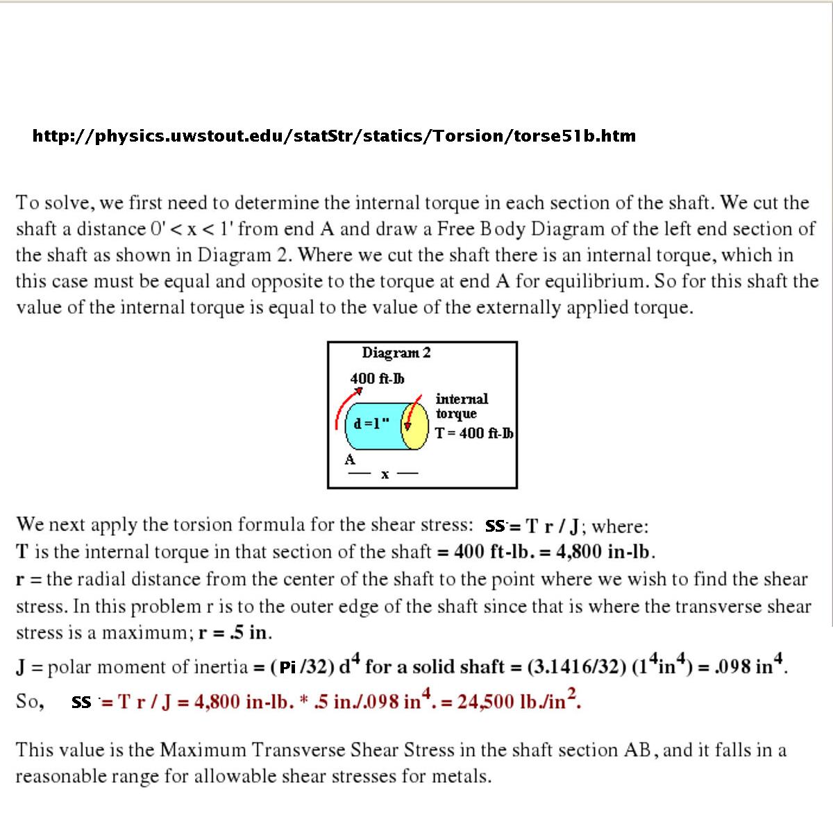
Lets design a shaft for five foot pounds as a first guess.
See the shaft stress chart attached.
Torque in inch pounds is five foot pounds times 12 or 60 inch/pounds.
Lets try a .2 inch diameter shaft so r = .1 inch. d is .2 inch of course.
d^4 = .0016
J is then 3.1416/32 X .0016 or 0.000157 inches^4
Shear stress is then 60 X .1 / 0.000157 = 38,200. Piece of
cake for 4130 steel.
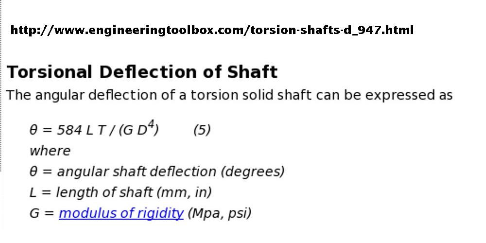
Lets see how far it will twist at 5 foot pounds.
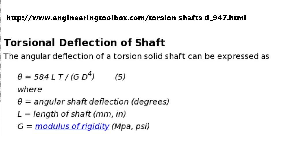
See the next attached JPG.
D to the fourth power is .0016.
Lets say the shaft is five inches long.
G the modulus of rigidity for 4130 steel is 30,000,000.
D^4 X G is 48000
So the angle of twist is 584 X 5 X 5 / 48000 = about .3 degrees.
Not much so it would be nicer if it twisted more. The stress is modest
at 38,000 psi so we could easily tolerate twice the stress so lets go
down on the shaft diameter to 3/16 or .1875 inches.
The thing you have to watch out for in a situation like this is
shaft whip. If the shaft is not perfectly straight it could fail
at 100,000 rpm due to the CG of the middle of the shaft being off center.
What would help is a hollow shaft that would twist a bit more
yet not have the same mass. That is why cars, like the Mazda RX8 are
going to expensive carbon fiber drive shafts. So the ideal shaft for
this purpose would be a tiny hollow carbon fiber shaft.
Too hard to make and temperature sensitive so we will stick
with 4130 steel. We could place a stabilizing ceramic ball bearing in
the middle of the shaft to prevent whip if it proves to be a problem.
I'll write a program to automatically calculate the diameter verses
the stress and deflection for a range of shaft diameters all five inches
long subject to five foot pounds of torque.
This shaft design could serve as the input shaft to the turbo compound
gear box. Unless you want to measure the turbine output HP in real time
the shaft does not have to be this small.
This small size is for dyno purposes only. What is truly amazing about
this thing is such a simple small key device can drop the fuel consumption
of a 200 HP engine 15% to 20% at a given HP.
Check my arithmetic.
Paul Lamar
The Rotary Engine NewsLetter. Powered by Linux.
ACRE NL web site.
http://www.rotaryeng.net
Youtube key word UTUBPLEASE
Copyright 1998-2008 All world wide rights reserved.