Hi Doug,
What is the status of your turbo compound work?
Do you have any pictures to share?
Paul Lamar
Paul,
Now cutting metal and making parts. Give me a few days and I'll send
you some pictures of the -O-ring insert, P-ported, in-housing injector
pictures.
A little history of this adventure for the new guys. The more I study and
design the more I realize I need to study. Or said another way "There
is a gap between theory and reality". Two years of conceptilizing, two
years of desiging and calculating, and now making parts.
Let me first say that I owe a huge debt of gratitude to Paul and the
rest of you guys that have basically brought me, sometimes kicking and
dragging to learn some basic facts about the rotary engine. My motto:
Designing and changing ones mind is cheaper than changing parts:) It
is actually faster in the actual hours spent. In design, I work on many
projects simultaneously but like to focus on only one during the
construction time.
The reality of my turbo compound work has been driven by the need to
create a compact, lightweight high performance engine that would fit in
and pull my extended wing SeaWind amphib over vast distances. And yes I
have actually been building the plane all along though sometimes it
seems I have spent more energy in sanding it away.
For fit, power and reasonable weight, a quick and logical choice would
be a P-ported 20B with the Bell 47 redrive. Relatively painless choice
and it fits with the standard length engine mount with a few millimeters
to spare. Note that Mistral's drive will require a new engine mount
because of its length. Increased fuel burn and hence fuel weight
combined with heavy engine weight would not allow the SeaWind to fly
farther than the Lyc. IO-540 equipped planes. Perhaps less. Fitting in
the heat exchangers would result in a less than optimum cowling size and
shape. Increased drag. Heat exchangers sized for cooling the BTU from
a 300hp engine will be the same whether that horsepower is coming from a
20B or boosted 13B, or so I originally thought. Read on.
This is where turbo-compounding shines because it is recovery wasted
horsepower. In other words a 13B putting out 300 hp that has 50 of that
hp coming from a recovery exhaust turbine will actually have the heat
index of a 250hp. This is significant when considering the amount of
heat that is wasted in the rotary. When we look at the history of
turbo-compound we notice that in development, a standard engine using
this technology evolves into a more efficient engine right across the
design board. Compression goes up, components become more robust,
cooling systems are enhanced and fueling becomes more precise.
Complexity however is added. So it is with the rotary. I choose the 13B
P-port path, frankly because I like 'the little engine that could
story':) Actually in its simplest configuration N/A at 6,000 rpm with
the proper cooling, fueling and rammed air intake design, this engine
will make at least 160hp. and that is enough to keep my plane flying for
a long long time.
Add an efficient supercharger, 10:1 ratio lighten rotors, better water
and oil pump, larger pre and post ducted heat exchangers, proper
detonation gun sprayed aluminum housings and a power recovery turbine to
the engine and suddenly the plane becomes a flying fuel tank, capable of
setting many world records in class. I am not interested in the
records, but would be happy to fly without getting my feet wet. Made
by the book Seawinds have been known to carry 240 gallons of fuel over
long distances, repeatedly. Yes this is almost 30% over gross but that
is the nature of flying long distances. It is not done every day or in
turbulent conditions in the first few hours of flight but this is the
reality of ferrying planes across the Pacific Ocean. Confirm the weather
patterns and then launch.
Amphibs. have the advantage of having the engine on a pedestal so
there is some leeway about the cowling size and component placement. I
have a goal to reduce the power plant weight (including PSRU and heat
exchangers) to at least 35% under that of the IO-540, and reduce the
cowling flat plate drag at least 30%.
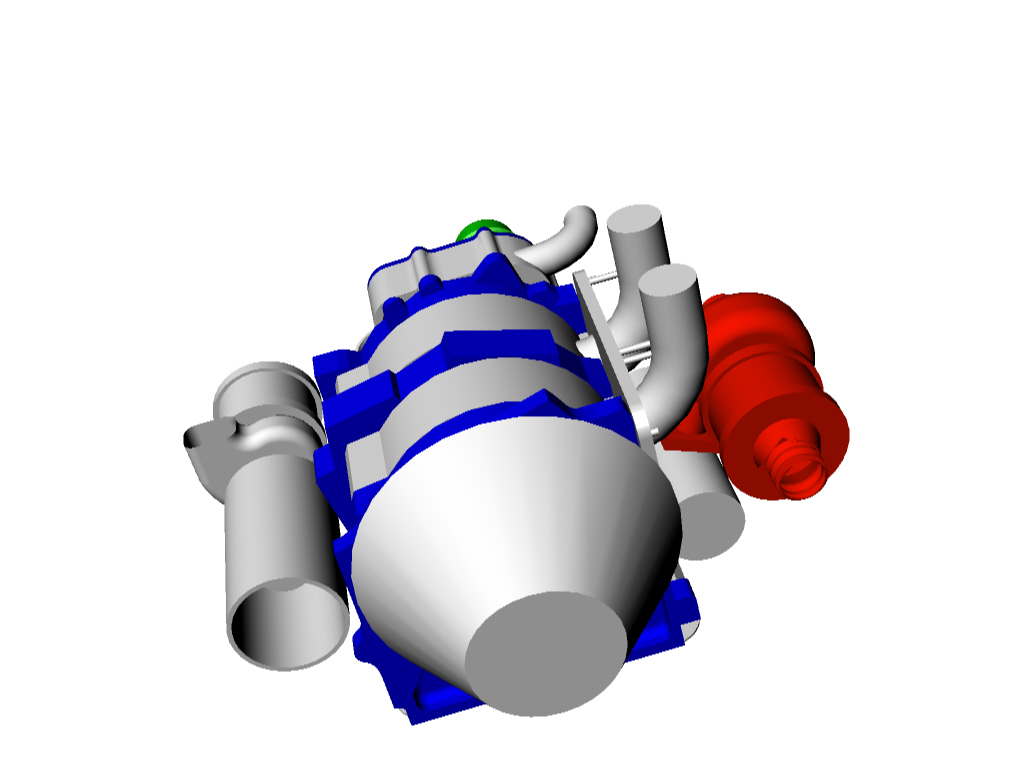
Shown below is an early Rhino software sketch I did to show component
placement. Turbine and attached modified ROTREX traction drive on the
right feeds the extra power into a multi-rib pulley with built in torque
isolators that is bolted to the e-shaft counter weight. The rotrex
drive and turbocharger need an interface plate as well as a low mass
semi flexible shaft to connect them. Design work is stopped while I
finalize a turbine selection. A spline in the middle of the pulley
accepts the input from the PSRU. The RX-4 Bell housing I am using has a
central ball bearing, then bearing sleeve and oil seal built into the
middle. This adds important support for the PSRU sun gear shaft.
A local aerospace firm is now building up the PSRU components. I
personally milled and modified the Bell housing already. The turbine is
the question. An axial one would be the most efficient but I am willing
to settle for second best and proven at this point. This might well be
a Turbonetic 60-1 with a P or even Q trim and ceramic ball bearings.
The split inlet turbine is mounted on a spin log chamber to: 1.
facilitate proper and robust positioning for the drive output, and 2.
act as a muffler when the turbine is bypassed and 3. channel the hot
gases in a way to avoid losing much kinetic energy but reflect sound
wave into the adjoining sections. The log muffler will want to move
when warmed up, and will be subjected to side loads of the output
pulley. It therefore needs additional support other than just the
exhaust port bolts.
Cooling will be a challenge under sustained 6,000 rpm power settings. Yes
bearing loads are at their lowest and friction losses are minimal but
power factors are up high and that heat has to go somewhere. Hence
double by-pass radiator set into the rear engine frame. Air comes in a
sharks mouth front scoop right below the nose and is divided into three
ducts. Central air travels under oil pan to the rear water heat
exchanger, and exits out the top. Side ducts feed side oil heat
exchangers exiting out the rear lower sides.
On the left is the rammed air intake coming from behind the prop into a
low resistance filter and then feeding a traction drive supercharger.
Somewhere in there will be alternate air and a supercharger by pass.
Supercharger is sized to deliver design boost at 18,000. Boost is
bypassed at low altitude (effectively unloading the supercharger) and
the bypass valve is dialed close at higher altitude or when max power
is desired. Alternator 1. is below the super charger. A smaller John
Deere alternator 2. resides where the present Mazda water pump outlets
are. New compact side feed, rear outlet BWM water pump location is in
front of the block intake hole. BMW timing housing now in hand to take
measurements from. The alternate power for the ignition system and one
of the dual leading plug comes from a small Generator on the
distributer shaft running at one half e-shaft speed. Voltage could be
around 60 volts dc. Design not finalized yet but this is a project left
to our company guys who specialize in generators.
Present engine project bottle-neck to allow actually engine assembly is
the finalizing and constructing a dual leading plug. Suggestions and
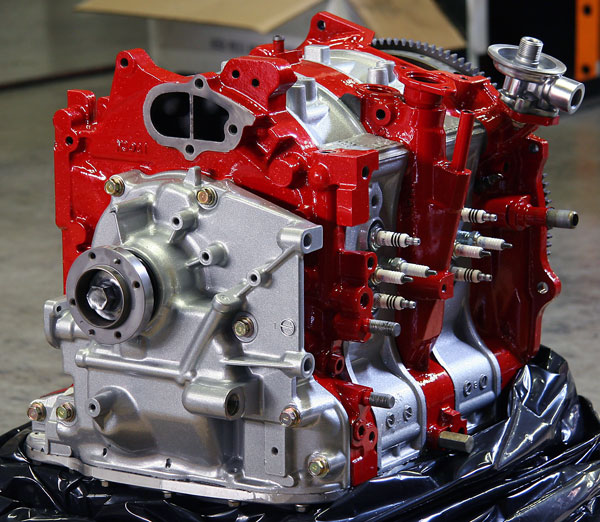
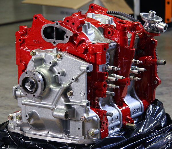
comments welcome. For your files I included an early Racing Beat eight
plug 13B engine pict.
Doug in Japan.
The Rotary Engine NewsLetter. Powered by Linux.
ACRE NL web site.
http://www.rotaryeng.net
Youtube key word UTUBPLEASE
Copyright 1998-2008 All world wide rights reserved.