<snip
I think it's use as a "magneto" built on the distributor stalk is
still the most interesting application.
-Vince Orton
Do you have a schematic of how it works? Is the small device on the
right
a trigger of some sort?
Maybe some one could come up with the equivalent of an impulse
coupling.
Did the Model T have a vibrator or something like that for starting.
Paul Lamar
Paul -
You're out of luck - no schematics on the 8.5x5.5", single-sided
pamphlet that comes with the unit. I could scan it for the group, but
I'll do you all a favor and rewrite what's in it below.
Igniter circuits should be all over the internet. However, testing
with the CC (cheap Chinese) unit should be okay for prototyping and
proof-of-concept.
Instead of an impulse coupling equivalent, you could battery-power the
igniter through a diode or bridge rectifier. We'd have to see the
magneto voltage output before resolving this challenge.
Original link for reference:
http://www.pccmotor.com/inner-rotor-kit-crf50-crf-50-ignition5050.html
*****
I'm breaking out the Chinglish-to-English dictionary to give you a
functional description of the PCC Motor "INNER ROTOR KIT CRF50 CRF 50
IGNITION CDI IR01" ignition system we have been discussing. I cannot
figure out some word choices like "bag", as in "connecting high
pressure bag end". "High pressure" is "high voltage", but I'm totally
guessing from context that "bag" is a spark plug.
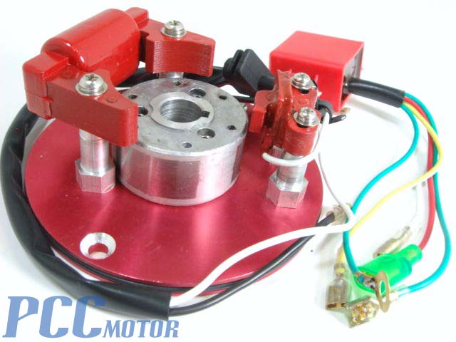
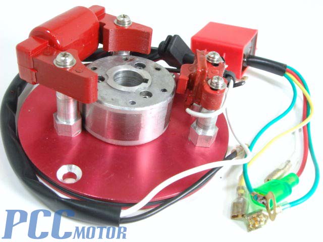
Refer to the attached photo.
1) The shaft-mounted rotor, with TAPERED shaft-hole. It is loose in
the photo, and simply sitting on the mounting plate. It has three
permanent magnets embedded within.
2) The magneto coil only takes up 180 degrees of the rotor's
perimeter, and is pictured on the left side in the photo. It has one
black wire for the magneto's output that goes to the igniter. I
assume the magneto's other electrical path is chassis ground of the
mounting plate.
3) The trigger is on the right side in the photo. It has 2 elongated
screw mount holes for variable timing adjustment. It has one white
wire for the trigger signal to the igniter. I assume the trigger's
other electrical path is chassis ground of the mounting plate.
4) The igniter is located behind the trigger in the photo, lying loose
on the tabletop. The igniter is a plastic epoxy-potted box with 5
wires:
a) red magneto power in
b) white trigger in
c) green ground (with lug)
... and as best as I can translate/guess ...
d) yellow high voltage spark plug lead
e) green ground spark plug lead
*****
Having discussed this for days now, I would suggest some serious
thought and testing before flying behind CC magnetos. I suppose using
the coil, trigger, and rotor would be alright - it beats manually
winding coils! But I'd probably redo the igniter with some solid,
beefy electronic components --OR-- test the hell out of the CC units
(plural).
Let me know if you want me to check out other units. If you're far
from Chino Airport, it's probably cheaper to order it online ($45),
since gas will easily outstrip shipping.
Here's a PCC Motor webpage with more ignition items:
http://www.pccmotor.com/engine-accessories.html
-Vince Orton
I am off to Florida tomorrow (16th)for a week to cover Bensen days, Mistral
Deland and Sun n Fun so I'll get one when I get back. Internally
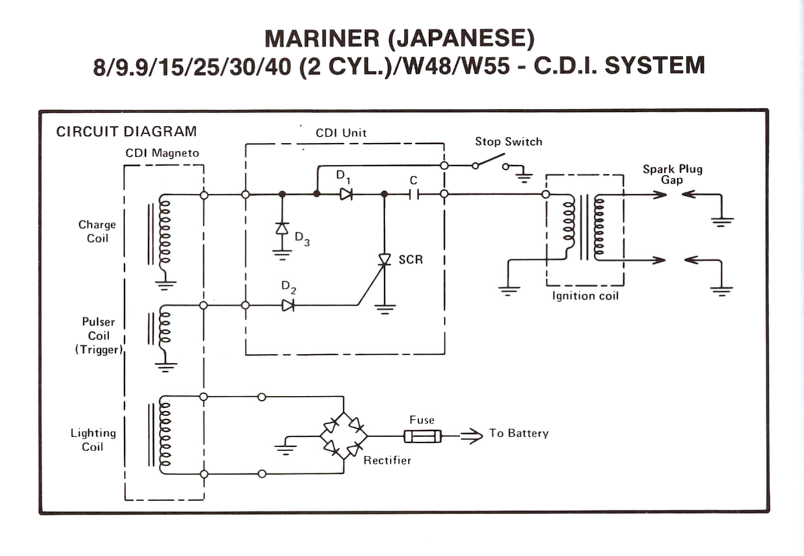
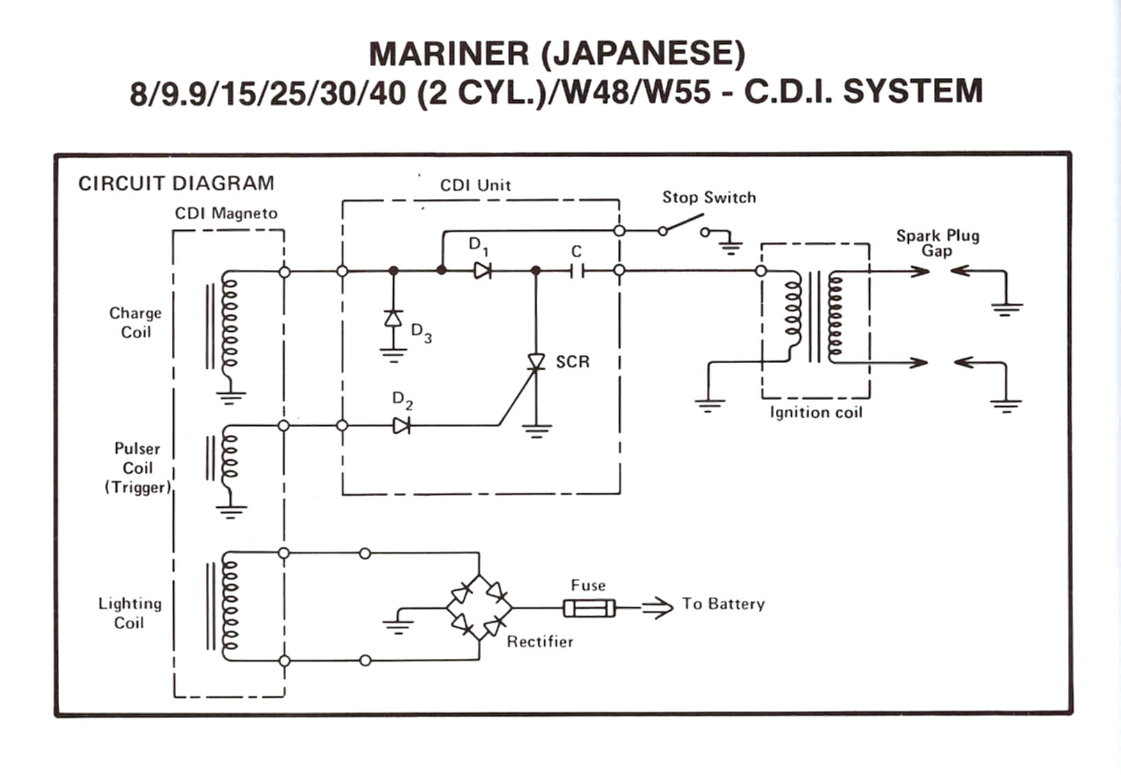
is is probably an inverted clone of the outboard motor CD system.
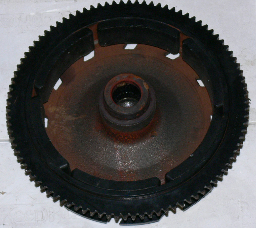
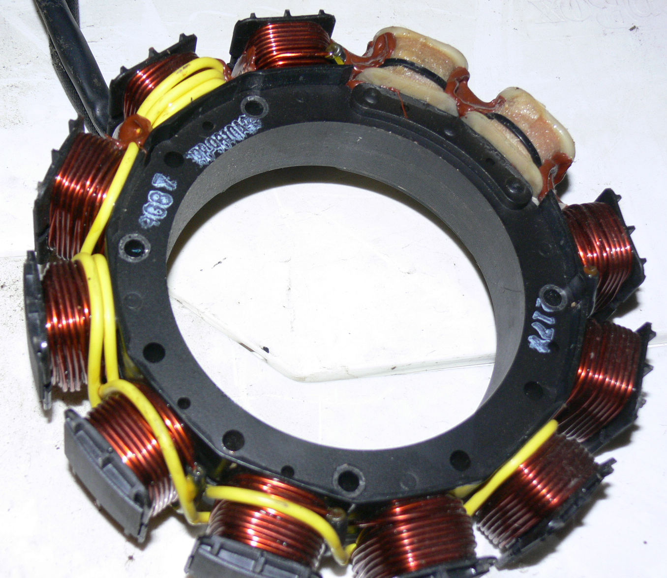
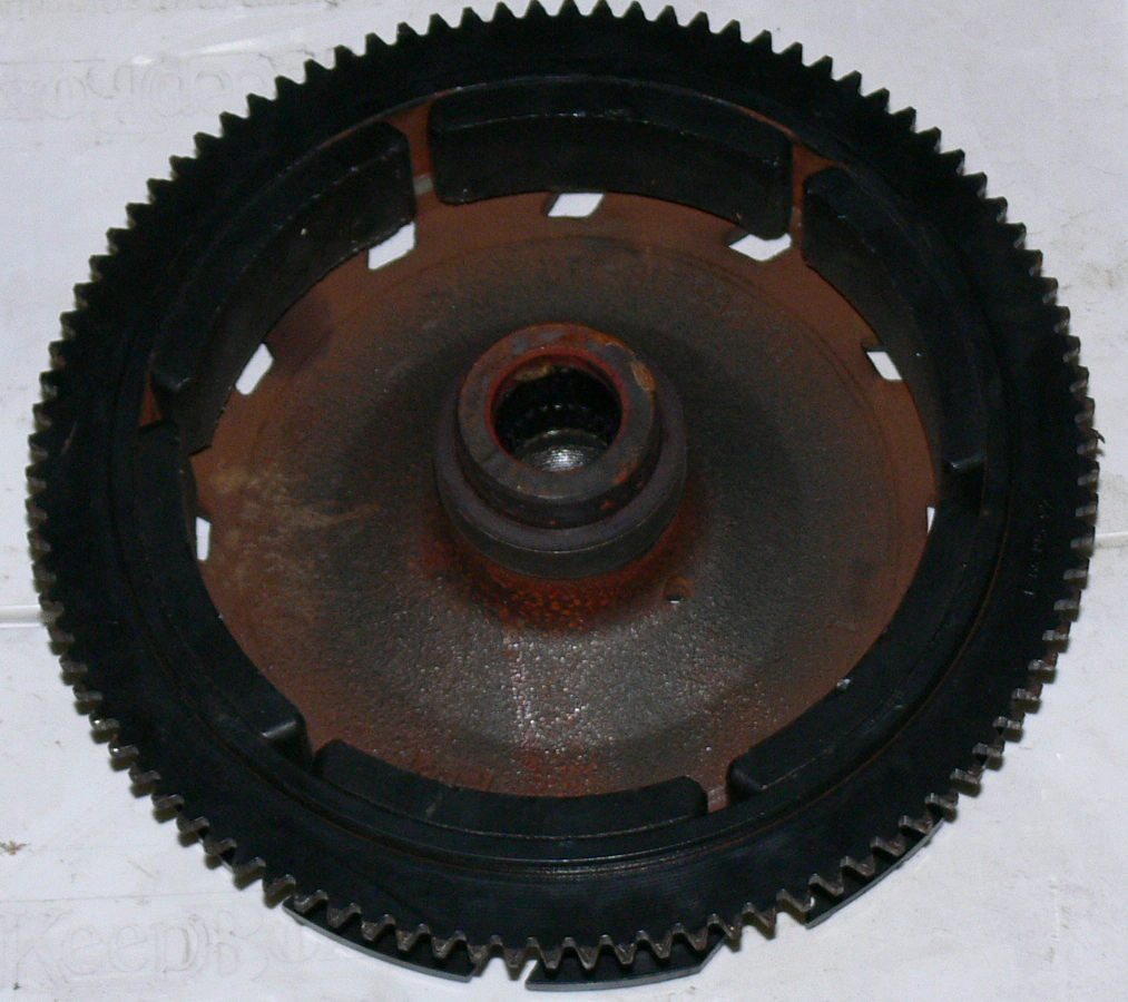
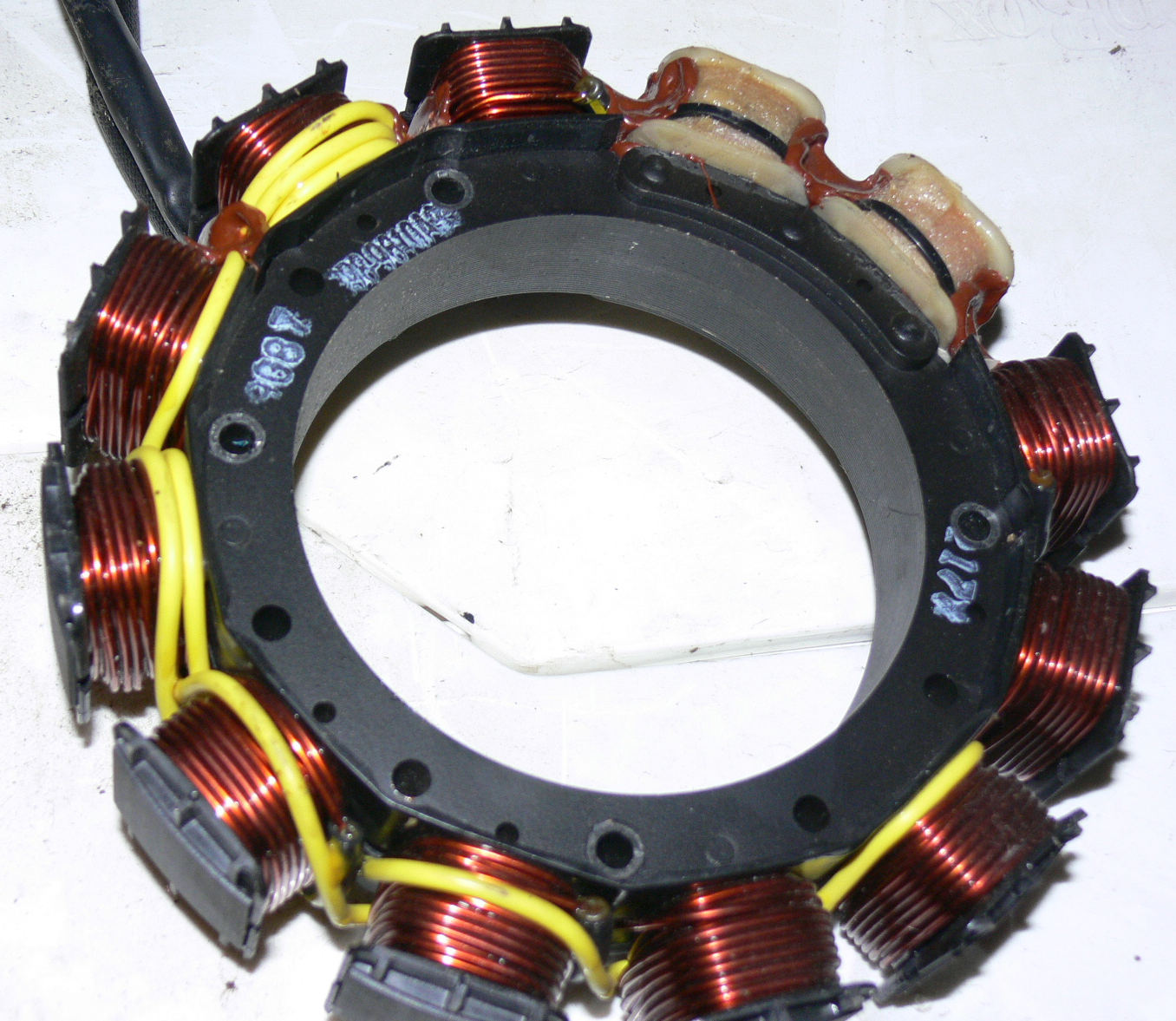
A larger magnet rotor would be better. Here is a schematic of the
outboard motor CD system.
Something like this would complement the Holley 2 barrel intake
system.
Paul Lamar
--
The Rotary Engine NewsLetter. Powered by Linux.
ACRE NL web site.
http://www.rotaryeng.net
Youtube key word UTUBPLEASE
Copyright 1998-2008 All world wide rights reserved.