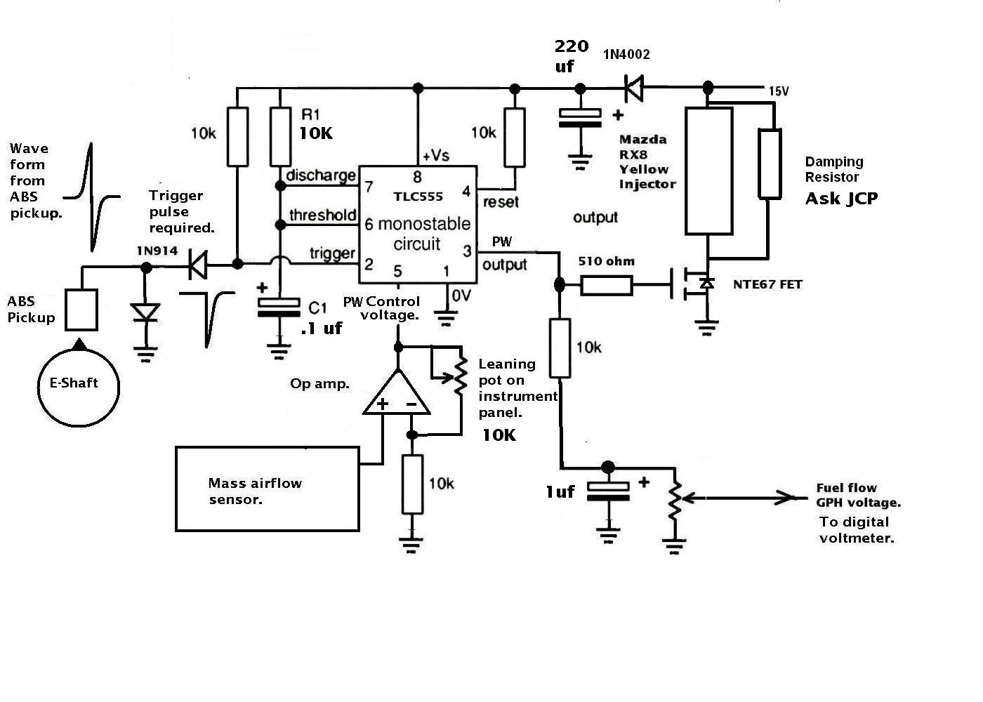
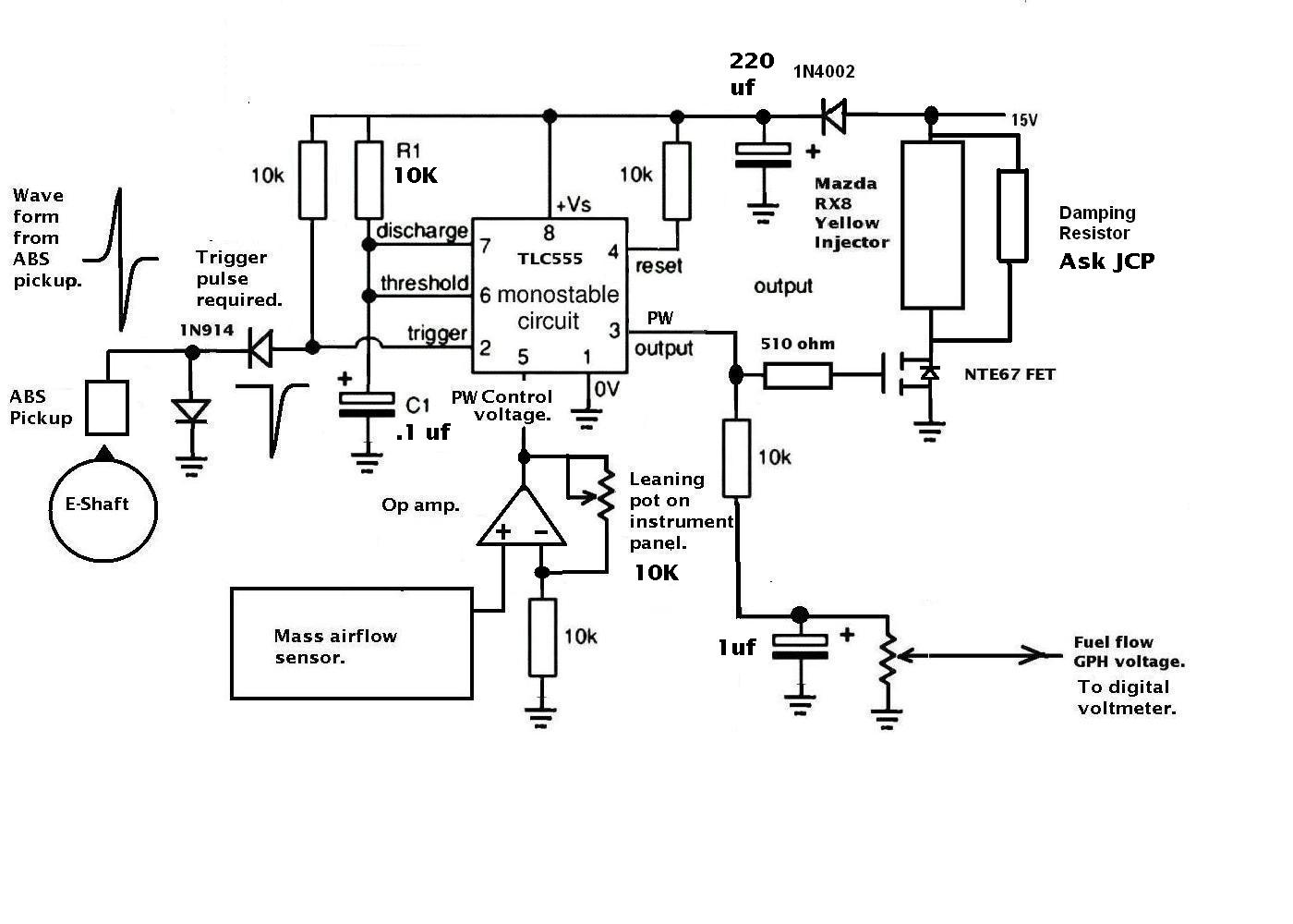
I am breadboarding up a version of your 555 circuit, and was wondering
if you could provide any ball park figures for the unvalued components
(capacitors, Leaning pot, R1 and damping resistor), or ball park pulse
width range.
I know the damping resistor was mentioned in an earlier post, but
I'm currently working from web-mail, and cannot access my archives.
I'm substituting a TLO31 for the op-amp, and a 2N6660 for the FET,
just because that's what I have laying around.
Do the injectors require fluid flows for self cooling?
Sorry to be a burden.
C. Smith
On the damping resistor ask JCP. I have no idea what
he has in mind.
Here are the remaining values.
-----------------------------------
ops forgot the drawing.
Here it is.
------------------------------
I don't think that op amp circuit is going to work.
I am going to get a Ti INA 122 instrument amp
and fool around with it. Minimum gain is 5
so I will probably try the leaning pot on the
input side of the inst. amp.
If you have a variable voltage supply I would feed that
into the TLC 555 for now. Just for demo purposes.
Paul Lamar
--
The Rotary Engine NewsLetter. Powered by Linux.
ACRE NL web site.
http://www.rotaryeng.net
Youtube key word UTUBPLEASE
Copyright 1998-2008 All world wide rights reserved.