The five volt on board power supply this thing comes with
makes it real easy to wire up.
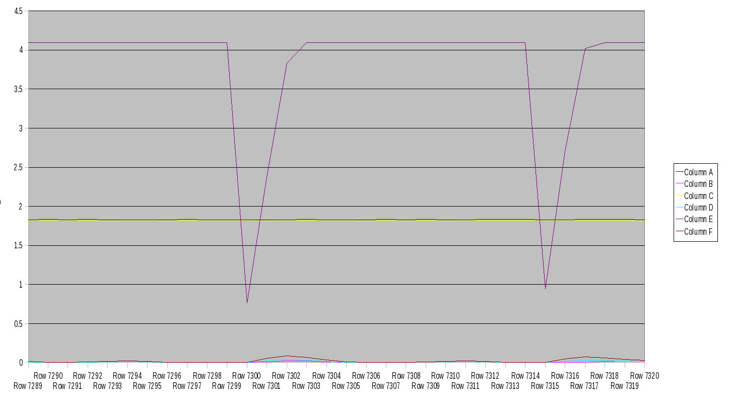
Here is the results of the first pressure sensor test. I used
a hand vac pump to reduce the pressure from sea level
to about 26 to 27 inches of Hg vac.
The numbers at the bottom of the chart are the sample numbers at
1000 samples per second. Data rez is to the nearest 1/1000 of a volt.
Seal level is 1.8 something while full scale is close to 4.5 volts.
This thing is real easy to use.
Mark, it would take all day to hand pump down a water jacket :)
-----------------------------------------------------
I connected the second pressure sensor.
I am not sure why but it had a different sea level
reading than number one. Curios. Of course #2 was looking through
the hand vac pump so there could be a slight difference there.
I'll have to record it with both wide open to check for sure.
Here is the data. Last couple of attachments.
I have to relearn how to plot in Open Office spred sheet as well
as learn more about how the data acq software works. It is coming
along well. The secret is lines without points :)
Things are looking good.
------------------------------------------------------------
There does appear to be some offset but I don't know why.
See the last attachment. The noise could be power supply
related or sound pressure related. These things are acting
like a super sensitive microphones. Loud noises make a difference.
The offset is on the order of .015 volts. I'll have to take a
look at the pressure sensor data sheet.
------------------------------------------
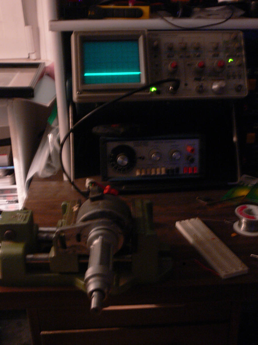
Well I got it all together. I used another analog
channel to serve as a TDC mark using the 2nd gen CAS.
I took the gear off the CAS so I could drive it with
a rubber band belt from a drill motor. I got it up
to 2000 RPM.
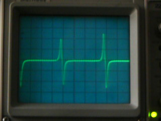
The output of the 2nd gen CAS looks just like an
RX8 CAS or a anti lock brake system sensor. They all use the same
principle.
I used an opto isolator for the trigger signal as I did not
want to risk grounding problems. The positive part of the trigger
pulse turns on the LED which turns on the photo transitor which inverts
the pulse. That is why it goes negative.
Here is some output data and a picture.
Paul Lamar
--
The Rotary Engine NewsLetter. Powered by Linux.
ACRE NL web site.
http://www.rotaryeng.net
Youtube key word UTUBPLEASE
Copyright 1998-2008 All world wide rights reserved.