The five volt on board power supply this thing comes with
makes it real easy to wire up.
Here is the results of the first pressure sensor test. I
used
a hand vac pump to reduce the pressure from sea level
to about 26 to 27 inches of Hg vac.
The numbers at the bottom of the chart are the sample
numbers at
1000 samples per second. Data rez is to the nearest 1/1000
of a volt.
Sea level is 1.8 something while full scale is close to 4.1
volts.
This thing is real easy to use.
-----------------------------------------------------
Well I got it all together. I used another analog
channel to serve as a TDC mark using the Mazda 2nd gen
RX7 Crank Angle Sensor.
I took the gear off the CAS so I could drive it with
a rubber band belt from a drill motor. I got it up
to 2000 RPM.
The output of the 2nd gen CAS looks just like an
RX8 CAS or a anti lock brake system sensor. They all use
the same
principle.
I used an opto isolator for the trigger signal as I did not
want to risk grounding problems. The positive part of the
trigger
pulse turns on the LED which turns on the photo transistor
which inverts
the pulse. That is why it goes negative.
------------------------------------------------
This last plot is only .4 seconds worth of data taken at 2
milli seconds
apart. Truly amazing. A super high speed camera shot of
what is going
on in the intake system. The blue and red lines are the
pressure sensors not connected
to anything. The yellow line is the trigger from the 2nd
gen
crank angle sensor. The yellow pulse happens at E-shaft top
dead center.
You can see the drill motor accelerating on the left of the
chart.
It peaked out at 2000 RPM.
I can hardly wait to test Mark's P-port engine. 1800
RPM to 6600 RPM.
To my knowledge this is the only time, since the book,
Scientific Design of Exhaust
and Intake systems was published in 1962, this level of
data was available.
In those days they used an ingenious rotary valve driven by
the crankshaft
to measure the pressure data from an intake or exhaust
manifold using
18 U tube manometers.
We will have data over a wide range of RPM's which was
not available in the
book. Mazda published just a snap shot of one cycle at one
RPM of a p-port
engine probably using an O-scope.
Paul Lamar
This is great work you are doing Paul. I was curious, with a 555 FI sytem,
and a simple constant pressure fuel supply, would there not be a tendancy
for the fuel mixture to grow richer (for a given RPM), with increase in
altitude?
Increase in delta P across the injector?
Could one of the pressure sensors (similar to those you are using for this
test) then be incorporated into the 555 analog section to sum in a
correction? I realize that with the mixture control, it can be done
manually, with egt monitor and pilot intervention. Just a thought.
C. Smith
That is done automatically by the return type fuel pressure regulator.
There is a hose running from the intake manifold to the pressure
regulator.
Paul Lamar
C Smith,
the main thing that keeps the mixture correct is the mass air flow sensor
(MAF). The "mass air flow sensor" is measuring the volume by weight of air
entering the engine providing automatic altitude compensation.
That is the real beautiful thing of hot wire MAF systems.
Larry
Tracy has speculated that the manifold pressure tap is behind the throttle
slide at part throttle so there may be some turbulence screwing up
the manifold pressure signal. I think it is plausible. We will find out
when we do the data acq test. Another possibility is the air flowing past
the pressure tap hole is acting like a venturi and sucking some of the
air out of the pressure sensor tube.
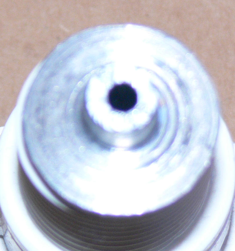
I made up some pressure tap devices to screw into the apex seal oil metering
holes we no longer use. I made them from a metric bolt.
These may solve the problems if either one of the scenarios is the problem.
In the process I incorporated a small hole to act as a damper. I hope it is
small enough but I doubt it. We also intend to try a couple of needle
valves in this regard. As the pressure changes from m-second to m-second
the air flows in and out of the pressure sensor tube. The small hole should
slow that process and tend to even out the peaks and valleys.
The hole size is .070 because that is the smallest drill I had.
My guess is it should be real tiny on the order of .010.
Don't be tempted to use the oil injector itself as that has a one way valve
in it. It won't work.
Life would be simpler if we just had a mass air flow sensor :)
Paul Lamar
--
The Rotary Engine NewsLetter. Powered by Linux.
ACRE NL web site.
http://www.rotaryeng.net
Youtube key word UTUBPLEASE
Copyright 1998-2008 All world wide rights reserved.