Hello Paul,
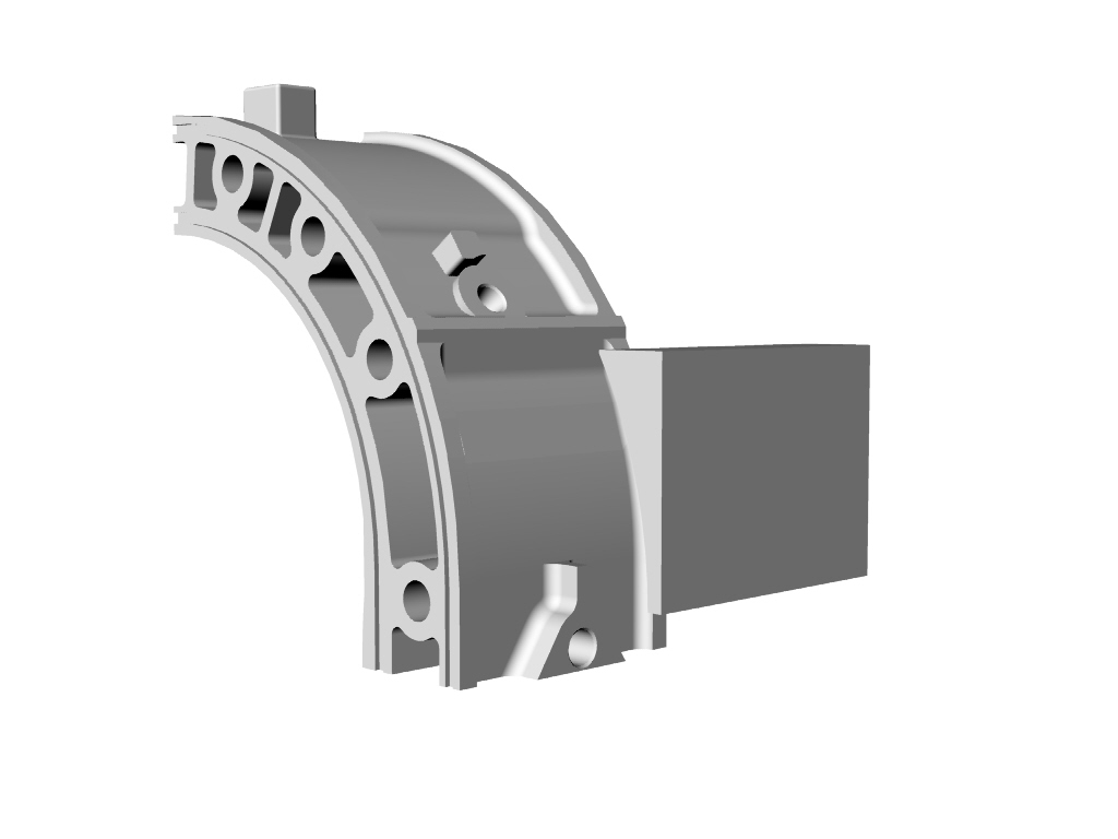
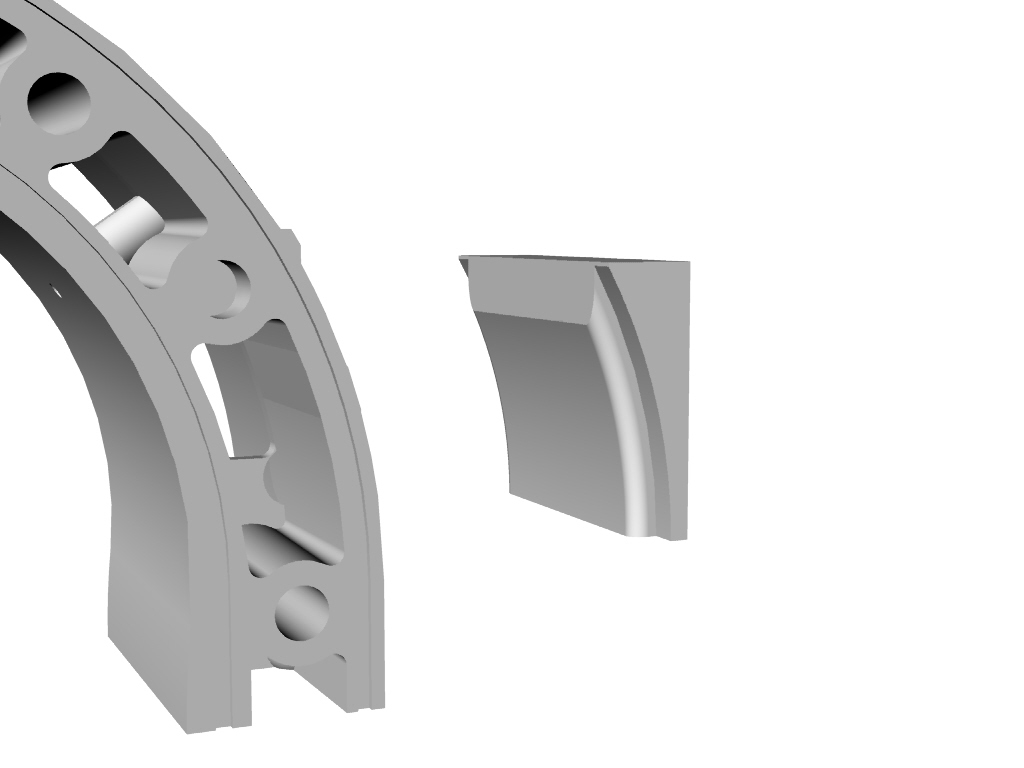
Here are four pictures of P-port and the in-housing injection holders.
This housing is one of several scrap housings I am machining to get the
entrance angle and component dimensions finalized. These four pictures
are from last August's work and don't show the finished bores yet.
The P-port will have an outer step bore similar to the injector
holders.
I am extremely happy with the hardness and toughness of the DEVCON Al
product. Only one trouble is the consistency is a little softer than
taffy so as you can see, it is easy to end up with inclusions. If you
work fast and use a technique like applying frosting on a cake, then
good results can be obtained. Any hole can be drilled out and filled.
The company sells another slightly softer epoxy that pours. I
assume it
has more solvent in it.
I was very happy with how the injector area worked out and was able to
get the correct and final dimensions with this one housing. As for the
P-port area I had to add about 6mm more along the bottom for the slide
throttle to be supported correctly. For this test work, adding
epoxy is
not a problem as it sticks to a preexisting epoxy when roughened up a
bit. As you can see it sticks well to prepared alumunim and is damm
near as hard. It machines VERY nice.
Can it done with your straight-in approach?Yes why not? Bend up
some
thin aluminum sheet into the proper wedge profile. Alodize it. Fix
this
fence in place with hot glue gun on the outside. Epoxy should be made
extra high and milled down to final dimensions. To save expensive epoxy
add a 40mm wooden or plastic dowel in the area where the inlet will be
bored.DO NOT PREHEAT to make it easier to pour. Follow the
directions for best results.
Doug in Japan
That 12.5 degree tilt looks like a real mechanical advantage.
I hope you can find a dyno over there to get some good numbers
on the pros and cons of your version. BSFC and HP.
Paul Lamar
Paul, With this approach why not bolt two housings together with a
center section between and the dowel pins then machine
that assembly P-port section flat so that a slide throttle can be hard
mounted directly to the housings?
Fred O.
I think I see what you are driving at. That might work.
I'll have to do a 3D and see if that is feasible.
Paul Lamar
Paul,
I bought the taffy consistency product. As Lynn mentioned years ago, and
repeated yesterday in almost the same words, the product held up in the
exhaust port area in his kart motor.
Doug Fir
I would like to point out that the bypass ports I built into Power
Products engines using Devcon Plastic Aluminum, move fuel air mixture
from the
crank case to the cylinder, and as such were cooled during operation. The
epoxy was exposed to high temperatures after shut down as the whole
engine
normalized the hot and cold sides. I have also potted Pport tubes (carbon
steel) in place and never had a leak. I have not attempted to use Devcon
in or
near exhaust ports. I doubt that it would hold up for very long in that
application.
Lynn E. Hanover.
I am going to try Doug's idea of putting epoxy on the outside
to make a flat area for an O-ring outer seal. If it leaks
in the future it can be more easily repaired. I'll buy the high
price liquid aluminum Devcon product but I am willing to bet it
is no better than JB Weld. I'll heat one puck of JB Weld and another
of DEVCON in the oven at 500 F and see what happens. My money is
on the JB Weld :)
The welded SS tube to the liner will be retained.
Paul Lamar
--
Paul,
OK but that may not tell you much as in application if your intake port
gets up to 500 degrees I think your engine will have bigger problems:)
I take it you are concerned with thermal soak after the engine is shut
down? This could be a problem with an unshielded exhaust system nearby.
I would be more concerned with comparing the compressive
strength,hardness, thermal creep characteristic, and toughness.
Are you going to retain the straight-in approach? If so the upper wedge
of epoxy will be about 15mm high. I suggest you put a metal dam there.
Best is a three side dam that conforms to the housing. This was the
next experiment I was going to try. It can be one piece stainless that
is bent. Done properly it will look nice as well and of course can be
milled as well.
Doug in Japan
Yes. I will keep the straight in approach.
Paul Lamar
Paul,
Is there any merit to a .005" interference fit between an Al tube and the
rotor housing using LN2?
Joe Berki
You have to be careful you don't stretch or warp the housing. .005 inches would
result in a major leak in the sides of the housing where the water O rings are.
IMHO it is not worth it. The SS tube tig welded to the liner and the conformal
aluminum plate is straight forward and highly likely to work with easy leak
repairs in the remote chance you even get a leak in the outer housing.
BTW a pound of Devcon pour came into today but I will probably use it
to make a casting pattern for the conformal aluminum plate. It was about $56.
Larry has a new casting supplier he likes in Northern CA.
Paul Lamar
Paul,
Before you start please understand one point. One of the main reasons I
went with a process of adding epoxy to the aluminum housing was I
wanted the chemical bond between the two creating a homogeneous
epoxy/aluminum housing. This was to ensure that four M5 (3/16") studs
that will hold the throttle assembly had enough material to tap into.
If you examine the housing area on the lower part of your bore and
about seven to ten mm in from the edge you can readily see that the
sloped housing profile is only about seven mm thick. Not enough for a
blind tap unless you are going to pot the inside of the cavity as well.
However with a epoxy material added on top of the housing you will
have added at least another six mm in thickness. On the other hand
slapping on a cast epoxy wedge with screws and silicon sealer will
ensure that you lose the strength advantages of the composite as well as
needing to screw into something that is screwed on to the housing. In
the end to have a perfect aligned fit you are going to have to machine
the housing with an end mill. Please don't tell me you are trying to
promote a quick and cheap drill press method P-port:)
Doug in Japan
Well no. Here is the plan. Mill off some material off the housing
down to the outer wall with the housing in the mill at 90 degrees.
Same as if you were boring the final hole. Screw this aluminum
casting (3D 1) to the out side of the housing. Screw holes or
screws not shown yet. Then bore the 2 inch
hole for the SS tube to be welded to the inner liner.
Weld the tube. Unscrew the casting slip it off over the tube
and cover the inside with red RTV and the bore with red RTV.
Replace the casting. Your done. Expansion and contraction will
not be a problem as it is accommodated by the flexible nature
of RTV.
I'll get a bunch of these casting made and sell them.
----------------------------------------------------
I changed the plan slightly. I was having too much trouble coming up
with a valid solid model for the casting pattern so I simplified it.
The down side is you will have to do a little die grinding on the rotor
housing to clean up the valley so a simpler plate will fit and work.
Let me me know if you want a stp file or iges.
Paul Lamar
--
The Rotary Engine NewsLetter. Powered by Linux.
ACRE NL web site.
http://www.rotaryeng.net
Youtube key word UTUBPLEASE
Copyright 1998-2008 All world wide rights reserved.