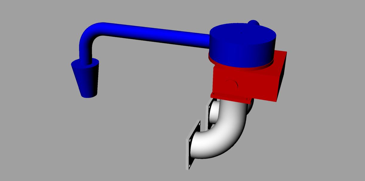
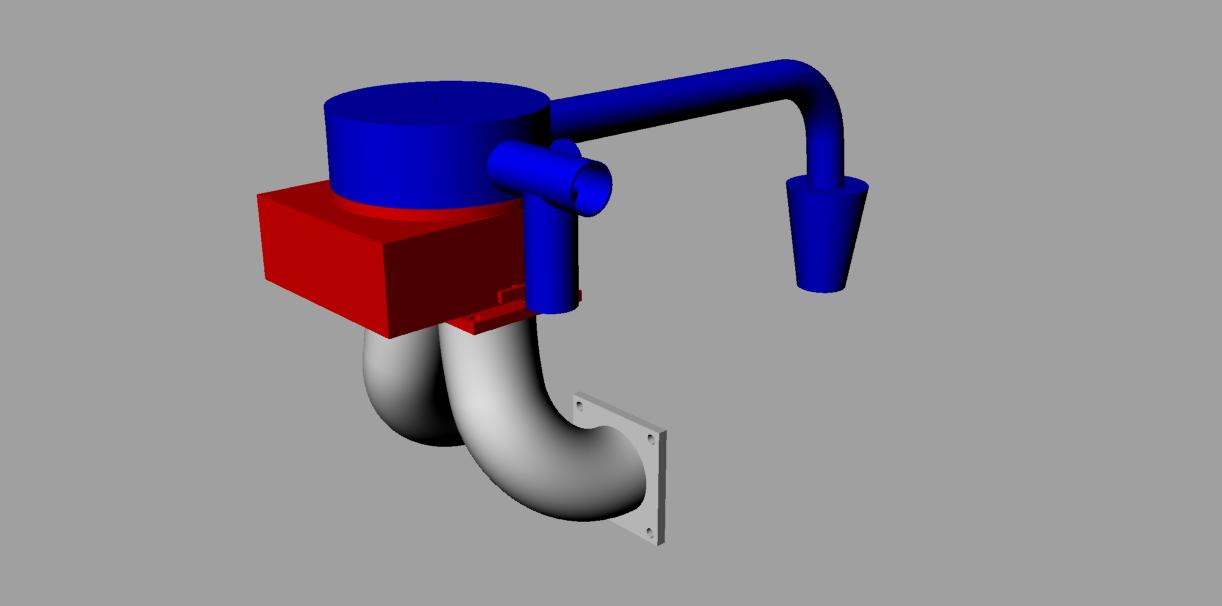
So I finally stopped being lazy and quickly put together a Rhino rendering
of my idea about the Holley set-up. The grey is obviously a intake manifold
for a PP rotary, the red is a crudely drafted Holley 2300 2bbl carburetor
and the blue is the rest of the intake system. The manifold and carb are
self explanatory but I figured I'd explain the blue system. Right above the
carb is a circular plenum with 1 outlet for carb heat and the other for
regular operations. On the carburetor heat side is a butterfly valve and a
dump tube like on other carb heat boxes. The other regular operations tube
leads over the engine and down the side before ending in a cone filter. My
idea is that by locating the carb in this manner, you lessen the chances of
any clearance problems with the cowl and have an easy route for carb heat
while still having a long intake to locate the torque curve in more
appropriate rpm range. I now that the dimensions are way off and that the
rendering is not very detailed but at least this could help better present
my idea.
Vlad
Good work Vlad. Glad to see you up to speed on Rhino.
How long have you been using Rhino. If just a short time you
are a fast learner. Please save and send them as jpg's as bmp's are too large.
I converted them this time but I had to go on the server and delete them.
The engine will run fine but the gray tubes are too short for optimum power
and lowest BSFC. The blue tube does not see the necessary pulsations
from the p-ports to trigger resonating. It might work if it were half
as long as it may see pulses from both rotors 180 degrees out of phase.
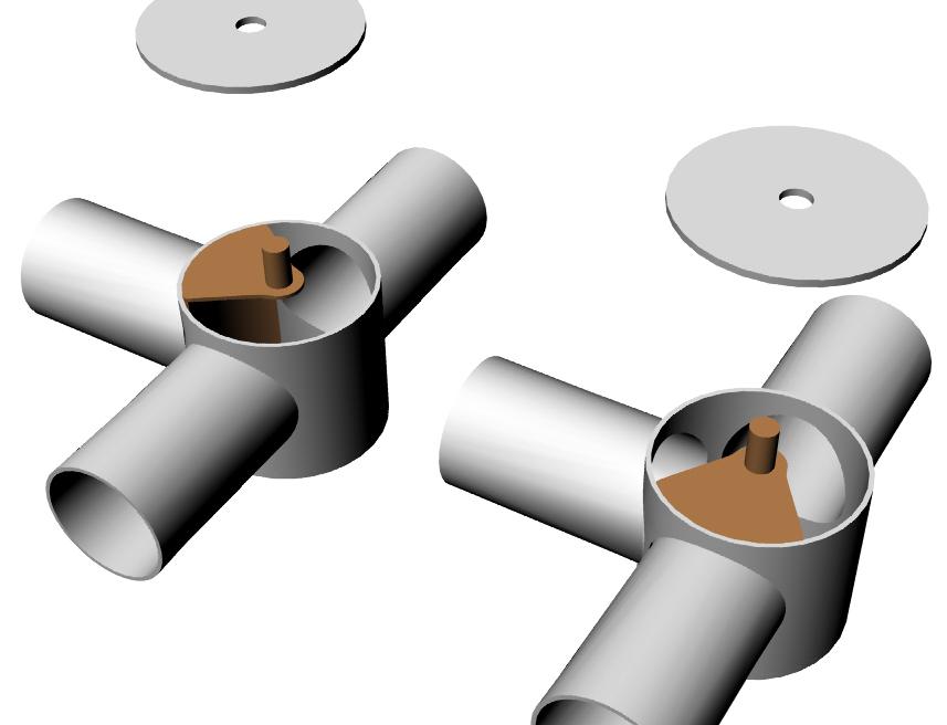
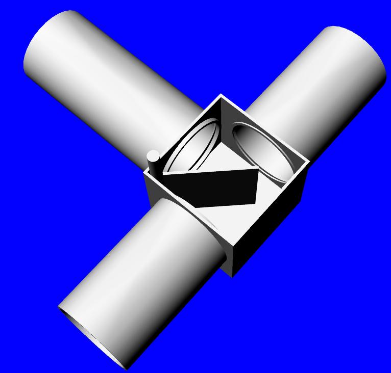
The last three 3D's are some ideas on carb heat and alternate air
valves we did quite some time ago.
Paul Lamar
The Rotary Engine NewsLetter. Powered by Linux.
ACRE NL web site.
http://www.rotaryeng.net
Youtube key word UTUBPLEASE
Copyright 1998-2008 All world wide rights reserved.