I am also thinking of mounting
one of the cheap $80 12 bit AD to D data acq system back there
with the USB interface to monitor the 555 EFI system and its
sensors on a notebook computer. Add a few ten dollar pressure
sensors and lots of things are possible. The A to D can also handle
the fuel flow read out and fuel totalizer in software.
http://www.hytekautomation.com/
I just came up with another idea using a tiny electronic load cell
out of a cheap bathroom scale incorporated into the motor mount to
measure prop torque. Knowing prop torque and prop RPM you know HP
out of the gear box. The A to D system can measure that as well.
I got the idea by watching the TV program Deconstructed on the Science
Channel. I'll appropriate Robin's bathroomscale :)
-----------------------------------------------
Here are some pictures of the load cell in Robin's bathroom scale :)
I'll have to buy her a new one at $34.
It is battery powered for the life of the scale in that black container
behind the LCD read out.
I'll work on a 3D dwg for the mechanism for the end of the S-beam
motor mount. One side has all the load due to engine torque.
The 12 bit A to D has such a high res and a wide dynamic range
it does not matter if it is measuring the weight of the engine only
when the engine is not running. The trick is have it bottom out mechanically
so it does not damage the load cell during hard landings and high G pull up loads.
That would be like having an over 300 pound person standing on the scale.
Paul Lamar
Hi Paul,
Those things like to turn themselves off after a few seconds. The ones
I have make you tap the scale, then it goes through several seconds of
a power up sequence. You may have to figure out some way to bypass the
automatic power feature and supply a larger battery.
Bob W.
--
N93BD - Rotary Powered BD-4 -
http://www.bob-white.com
3.8 Hours Total Time and holding
Cables for your rotary installation -
http://roblinstores.com/
I figure I could use just the load cell part.
It is probably The crystal type.
The force is applied to a piezoelectric crystal
and you measures the voltage across the crystal.
---------------------------------------------------
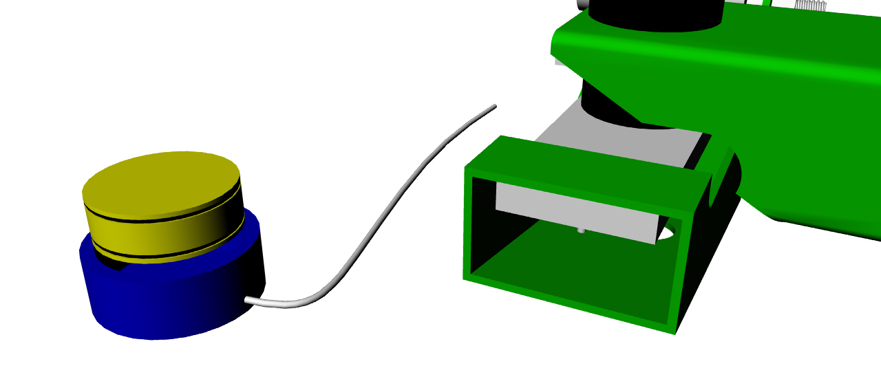
Preliminary design.
Here is what it would look like on the end of the S beam.
It is possible to retrofit an existing motor mount by
cutting off one cup and welding this on.
The lever reduces the load on the cell.
Does anybody see any problems with this?
Paul Lamar
Hi Paul,
You might want to add a positive stop on at least one side of the
load cell to prevent damage to the cell in the event of a
catastrophic down force on the lever. Dave M
Very good point Dave.
Not shown yet. I think I can use a small machine screw and make the stop adjustable.
I'll have to experiment on the bench and measure how much deflection the crystal
can tolerate. In this design it only sees about half the load but that may be way too
much for this crystal. The bathroom scale has a lever system that drastically
reduces the load on the crystal. I will need to research load cells
further. Still a work in progress.
I did add an up stop for the lever to keep turbulence from allowing the beam to jump
up. I also completely redesigned it as the first design used a narrow S-beam.
Current S-beams are 3.5 inches wide to pick up more oil pan bolts. I also
raised the pivot bolt.
Quiz: can anybody tell me why the pivot bolt needs to be in line with
the center of the rubber bushing? :)
BTW the output of the load cell can probably act as a prop RPM sensor
as it will see the engine firing pulses twice per revolution. It can also
measure the magnitude of the pulses for rubber coupling development.
----------------------------------------------------------
I looked into the load cell a bit further and most are $400 to $500.
The max output voltage for a 250 pound load cell is 250 milli volts so that
is a far cry from what we need. We need zero to 5 volts for the data acq
so an amp would be required with most load cells. The pressure sensor we
used on the manifold wave test is $10 and they can be had up to 100 psi. They
have the required zero to 5 volt output with an amp built in.
So here is plan B. Use a simple 2 inch diameter piston
which gives an area of 3.1416 square inches. At 100 psi the max
load is 314 pounds. We have a two to one lever so max load is
really 628 pounds. More than enough. A small hose going back
to the pressure sensor and data acq system is all the "wiring" that is
required. An occasional check on the fluid level is all the maintenance
required. Some sort of inert oil is required to be compatible with the
pressure sensor. Teflon O-rings will cut the friction in the system.
Paul Lamar
-
The Rotary Engine NewsLetter. Powered by Linux.
ACRE NL web site.
http://www.rotaryeng.net
Youtube key word UTUBPLEASE
Copyright 1998-2008 All world wide rights reserved.