Paul,
I want to set up a flow bench to do comparative testing between a slide
throttle and a rotary barrel throttle I am machining now. The slide
throttle is wonderful but as Jerry mentioned years ago with an angled in
approach wrapping the manifold closely over the top of the engine
becomes more challenging. My design eliminates that problem as the
manifold comes in from the top. Each throttle becomes an angled
manifold as well. Present device housing width with 50mm dia. ports is
about 72mm wide and 76mm in diameter. Port tube are 2" NPS threaded
and screw into the throttle body. For a sectional view imagine a
compass circle with north straight up. At the 270 degree location is the
center line port going into the engine. At the approx. the 40 degree
center line is the inlet. The inside rotating barrel has a passage way
through it. I plan to test two versions of barrels. These are solid
cylinder with passageway milled out, and a hollow tube with inlet and
outlet holes cut out. Short shafts are pressed into the ends of the
barrel and extend through miniature sealed bearings to the outer
housing. The shafts connect to the driving mechanism and/ or to its
neighboring throttle.
Instead of using a manometer I was thinking that using a MAF sensor would
be wiser as the info can be stored in computer program and I could test
the unit I want to use. To create the flow I want to power up the
supercharger with an electric motor and get some data on hp. consumed
verses flow as well.
If you like I can do a side by side test with one of your slide throttles
and get some flow verses section open area data. This information is
valuable in identifying possible turbulence issues at partial throttle
openings.
I could use some info on the $61, ('02 5.4l V8) Rock Auto MAF sensor you
bought $61 Colin.
What size ID is it?
Doug in Japan
That is a good idea Doug. In effect you are reducing the radius of one of
the
two 90 degree bends. I am looking forward to the results from the flow bench
test. How are your Rhino skills coming? Can you do a 3D for us?
Paul Lamar
Is something like this what you have in mind Doug?
--------------------------------------------------
Or perhaps this. If this it is going to affect the pipe resonance
and hence the power IMHO.
BTW the same organ pipe phenomena can help the turbo compound if the
exhaust pipes are resonant IMHO. We might be pleasantly highly surprised :)
-----------------------------------------------------
There is a leak when the throttle is closed on this 90 degree version.
That may go away with a greater than 90 degree angle which would
be your case.
What is the angle of your p-port tube Doug?
Paul Lamar
Paul
Often these types of throttles are straight through and akin to water
pipe ball valves. A 90 degree elbow as you depicted on your illustration
is not desirable in my case as it makes the throttle body housing huge,
and requires welding bosses to accept the ports. It also as you found
out won't close the port completely. A 1/3 to 2/3rd ratio is close to
ideal if you want the ports to screw into the housing on the radials.
That means the inlet is a about 118 degrees or less away. While this
seems less than ideal because the manifold has to wrap around more
than ninety degrees, remember in my P-port design is already angled 12.5
degrees up. I used the dimensions I did to clear the in-housing
injector rail by 6mm and have the manifold come out right on top of the
rotor housing.
If you use my dimensions stated in the previous note, the throttle will
close with about 5mm to spare, and will be very compact and singlular
which is a good thing I believe for ease of alignment and for three or
four rotor engines. The downside, (there is always a down side) is
compactness equates to a rather sharp corner on the upper inner lip of
the throttle. The inlet and and outlet threads almost touch at the top
and have only a slight radius put in by hand.
ASSEMBLY:
The in-housing port insert tube screws into the slide throttle body. In
my design the P. port tube becomes part of the throttle body and is
inserted through a previously affixed circular aluminium collar on the
housing. Two pieces, the collar and throttle body-insert combination.
The collar holds the outer housing O-ring in place using 4 screws, three
of which go into the aluminum ribs remaining on the housing and the
other upper one into the epoxy aluminum composite. This is another
reason I chose the orientation and angle of the P-port where I did
because I wanted something strong to tap into. The inner and second
outer sealing O-ring is on the P-port insert tube as explained in
previous posts. The outer 0-ring interfaces with the collar. The
throttle body/ port tube combination is held in place by several set
screws radially traversing the collar. I chose 50mm ID and 56mm OD for
the port tube but it could be a 4mm smaller or 1 mm larger.
Hope this helps. I am off to Tokyo today with Michiwa's computer to see
if I can reinstall an English System WINDOZ XP and if successful Rhino.
Here computer comes up with English prompts so I suspect the Japanese
version of XP is some type of screen translator program on top of XP.
Character code is two bit I am told to be able to display kanji.
Doug in Japan
As for room above the engine the sky is the limit but I want to keep
everything tight. This translates to oval epoxy tubes over the top and
a custom cowling. SeaWind cowling is enormous. It would insult the
rotary engine to use it:) Sort of like popping the hood on a 57 Chevy
and seeing all of that empty space next to the small six banger.
Doug in Japan
Don't compromise the HP and the BSFC for ego reasons :)
Paul Lamar
Paul,
Stay with round tube and reduce wall resistance. Understood. Actually
since I am supercharging organ pipe tuning doesn't come into play
compared to decreasing restrictions hence pipe size and length bigger
and shorter respectively would be the plan. I would like to go with a
combination manifold and throttle part on the P-port or better yet
within the P-port itself.
Within the housing a butterfly valve ala Steve and Everett could have
reduced restriction by increasing the diameter of the pipe a bit to
offset the flat plate drag of a 6mm thick rectangular cross section when
its open. Insert goes from 52 ID down to 50 ID after the throttle.
Another possibility is a flap valve hinged on the bottom and flipping
outwards. This idea is still half baked and I haven't thought it
through much I have to admit but it would be nifty to insert a throttle
unit and have it seal the outer surface and be done with it.
Doug in Japan
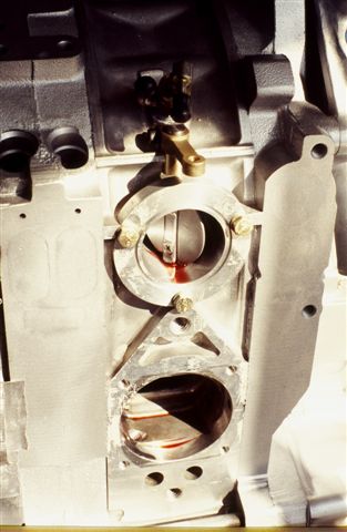
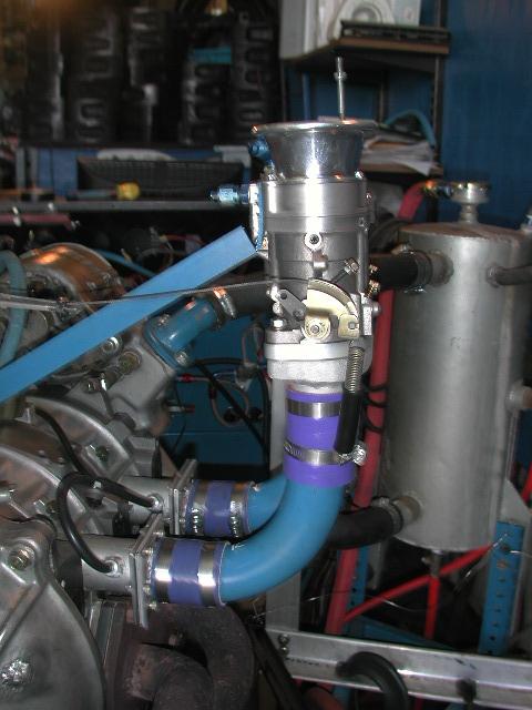
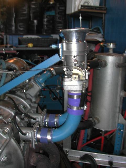
Doug--If it would be helpful, here is a photo showing detail of our port
insert with throttle shaft and guides. The red stuff is assembly lube. It
is a lot easier to make an outboard throttle assembly that bolts to the
assembled power section with the throttle shaft(s) centerline placed as
close as possible and have the butterflies clear. Sounds as if you may
already be working on such a unit. We had the preliminary sketches of it
going when Everett died in 1997. The plan was to test it in an attempt to
further reduce costs of producing the Mazda conversion engines if there were
no significant operational penalty. The throttles in the rotor housing/port
insert work exceptionally well but the complexity and man hours to do it are
a royal pain. Hopefully there will not be too much trade off by moving the
throttles out the minimum distance. Will be interesting to compare dyno
results of the two different configurations with all else being the same.
Steve Beckham
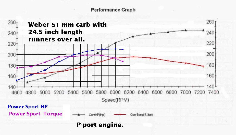
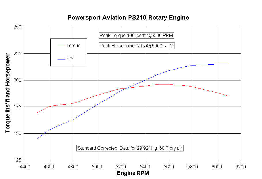
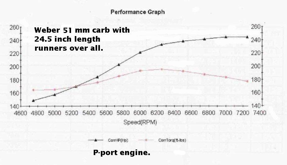
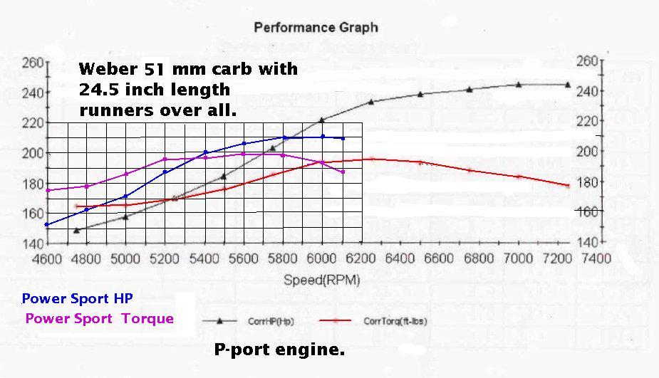
We have the dyno results of the new Power Sport engine verses
a 51 MM Weber carb Steve. The new Power Sport published
dyno sheets on the throttle-in-the-port version. Here it is.
The main difference is the the diameter and length of the runners.
The Weber runner length was 24.5 inches and the ID of the runner was 1 7/8th.
Do you recall what sized runners you used? The length of the runners?
We have data that suggest the diameter of the tubing also enters into the
RPM where the peak torque occurs. One would think it is only a length
phenomena. Of course the larger the tubing the less the internal
aerodynamic drag.
I expect the slide throttle Tracy EFI to be slightly better which Mark Suspinski
is running now. Standoff was low. It should be flying any day now. Idle
seems to be about the same as the new Power Sport engine. The p-port
13B Weber version idled like crap on the dyno. Standoff was moderate.
The RX8 p-port idled pretty good with the Weber as there is the same lack
of valve overlap as the 13B side port engine. Standoff was high. We don't
have real accurate HP data on the RX8 Weber but subjectively it was higher
than the 13B Weber version at the same 7500 RPM. I suspect two things.
One; the compression ratio was higher and two; there is much less port
overlap on the RX8 version. My guess is the RX8 Weber version is
around 260 HP. We did see 264 HP but the data was suspect.
Therefore the Holley 2 barrel will work best with an RX8 p-port engine.
Sort of old meets new :)
Paul Lamar
--
The Rotary Engine NewsLetter. Powered by Linux.
ACRE NL web site.
http://www.rotaryeng.net
Youtube key word UTUBPLEASE
Copyright 1998-2008 All world wide rights reserved.