Doug, this is what it looks like. I'll try to get into
the manual to find
out the pin-out functions.
C. Smith
Thanks. Some air appears to have to flow through the
device adding to
restriction or enlargement of the manifold. What size is
it? Do you
have an idea where it was place in the system? I am
guessing the air
box.
Doug in Japan
Doug,
On the fords, they are mounted in a 75mm dia plastic tube
with the air
filter on the inlet side. That is for a 220 to 285hp engine
series.
For the rotary, make a 70 to 75mm tube with a fabricated
flange to mount the
air flow sensor. that will size it for up to 300 hp. Above
that we go to the
Lightning 90mm body with the same sensor.
The 90mm lightning sensor body is good for 525 hp before it
is maxed out.
It is better to be a little on the big side than small.
When tuning we never
want the sensor output to be over 4.5 volts. the sensor
"rails" at around
4.75 or 4.8 volts, and then just flows more air without
telling the computer
you need more fuel.
Mount the tube on the inlet of the air box feeding the
tuned inlet tubes.
ideal size for the box should be at least 4X the volume of
the combined
tuned tubes, and more is better due to the strong pulsing.
Let me know if you need a model or drawing of the setup, as
I have a
lightning unit on the shelf that I can measure and draw up.
I need to get together with Paul so he can publish a good
"do and don't do"
list for using the ford maf sensors. used correctly, they
are great. set up
wrong..... things go lean and ugly in a hurry. been there.
Larry
Larry,
Thanks. I'll be in your neck of the woods in early June
replacing the
starter motor on my other bird. So I may be able to drop
by if you have
time for lunch. As my rotary engine could very well be over
300 hp
occassionally I think using the larger Lightning MAF 90mm
is a good
idea. A picture of the device would help as I know you are
a busy guy.
Yes I agree on the air box size info. Shape is also
important I'm
told. The racers here often use a large tube with hemi
spherical end
caps. The 20B was boosted so the box was smaller but
shaped the same.
Air like water takes the path of least resistance the only
way to
confirm the airflow is balanced in the manifold is to flow
test them.
I am still not exactly clear on how to create the engine
fueling map
when an engine is boosted. I'm using the MegaSquirt
device which
allows for custom formulae to create fueling tables. I am
guessing I
would still have to sample MAP or actually deck pressure to
tweak the
MAF sensor data which calculates flow based on known tube
diameter,
temp, and air speed. Perhaps having both sensors nearby
each other would
be the best of both worlds.
Doug
Larry,
I found it on E-Bay.
http://tinyurl.com/o6na5k
Doug
Here are some more, I think the 90mm is a bit less expensive here.
http://www.blueovalindustries.com/products.php?catID=9902232
C. Smith
Larry or Craig,
I am probably going to order the 90mm diameter MAF sensor as it has less
restriction than the 61mm unit. Do either of you know how to calibrate
it or does it come calibrated assuming it will be used flowing into an
Ford airbox?
Thanks
Doug
Doug and Paul,
Megasquit has some good info on MAF. It specifically has data on
the 'Ford MAF' and the 'Nissan Inifnti Q45 MAF' Sensors.
"http://www.microsquirt.info/mafmap.htm"
I am still here,
Blake
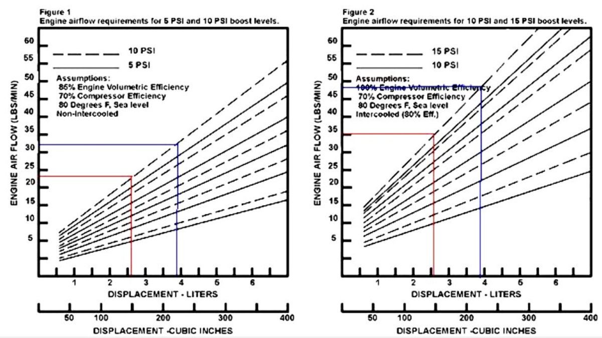
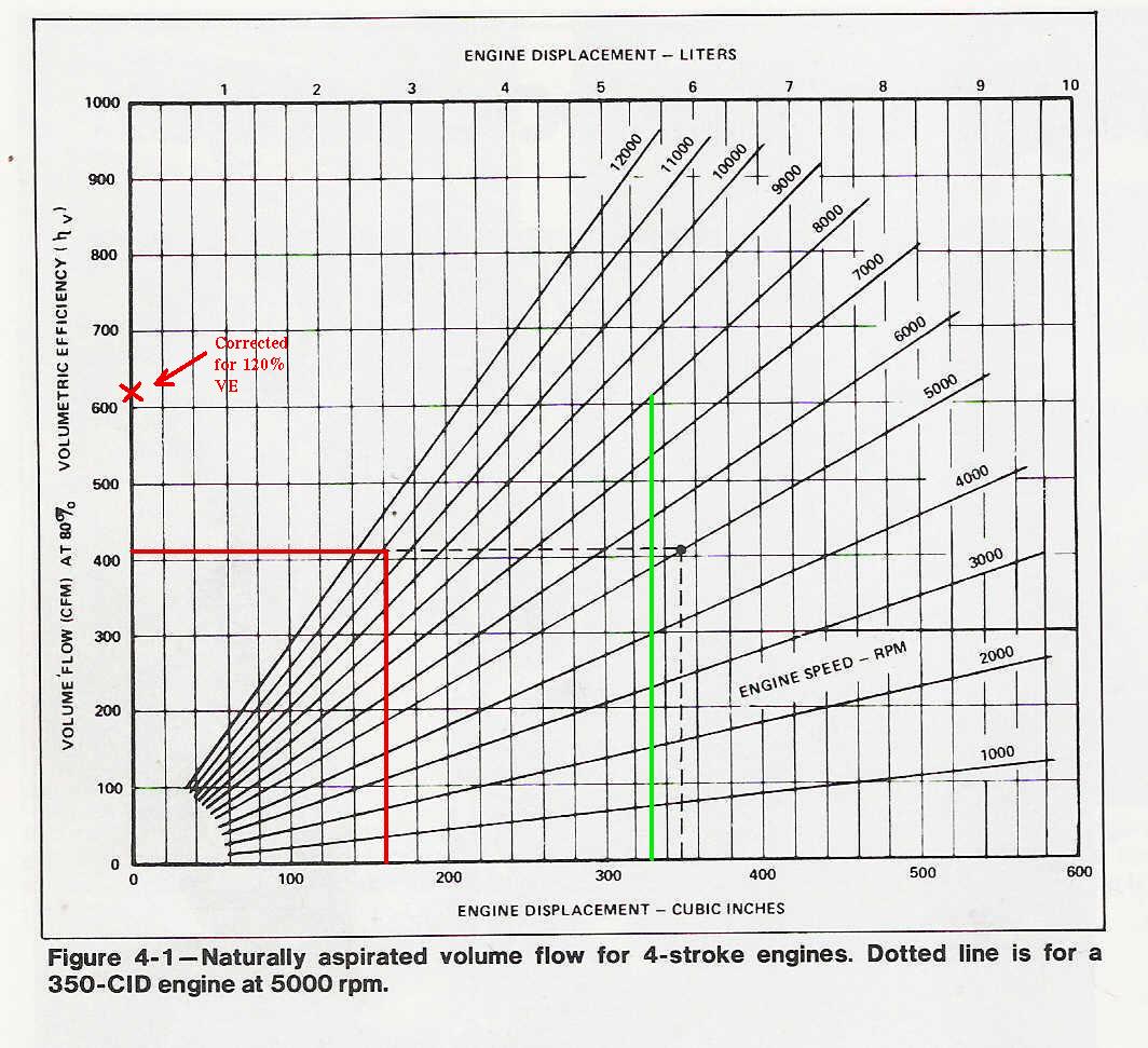
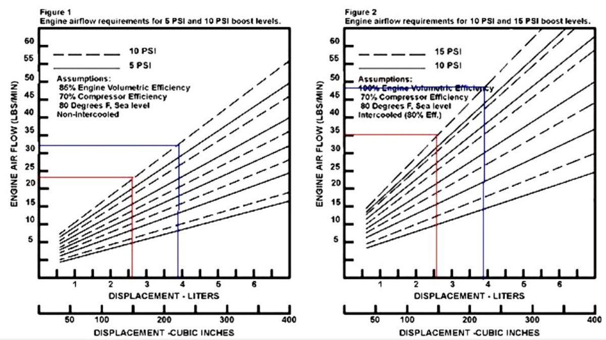
I converted mg/sec to pounds per minute which is more common
form in most of the old books on engines.
Switching to the metric system is a nightmare because of this.
-------------------------------------------------------
At 70 °F and 14.696 psia, dry air has a density of 0.074887 lbm/ft3.
So I used that number to add to the Ford MAF chart.
We have a lot more CFM data on engines than anything else.
Paul Lamar
--
The Rotary Engine NewsLetter. Powered by Linux.
ACRE NL web site.
http://www.rotaryeng.net
Youtube key word UTUBPLEASE
Copyright 1998-2008 All world wide rights reserved.