Paul,
Attached are some pics of a mock up of a two stage plenum that
ducts air from a scoop under the strake and turns it 180
degrees, passes air through a filter and dumps it into the
alumium portion through a MAF sensor out of a Lincoln Town Car.
The intake runners are 22" long to the port opening at the rotor
housing. I mocked up the aluminum in poster board . The
injectors go in the plenum on the intake runners. Would
bell mouths be required at the ends? The cold side with the
filter will be the composite unit in the pic. It will be bonded
to an aluminum bulkhead that will serve as a mounting location
for the MAF and the filter housing. I made the housing adapter
out of carbon fiber so a hose clamp that was included could be
used to secure the filter. Thanks for any help.
Joe Berki
Limo EZ
13b P Port
555 EFI
Looks good Joe. Carve the bells out of foam.
I updated the section on the web site about composite intake
manifold.
http://www.rotaryeng.net/carbon-fiber-intake.html
So have another read for ideas.
A recent idea is use 2 inch ID CEET flexible Neopren ducting from
AC Spruce for the runners. It is smooth inside and is resistent to fuel
vapor unlike the silicon stuff. Use straight sections of .049 wall
2 inch OD metal tube where ever possible and connect them with CEET
for the curved sections. Page 203 on the 2009 AC Spruce cat.
Cheaper than aluminum bends.
Paul Lamar
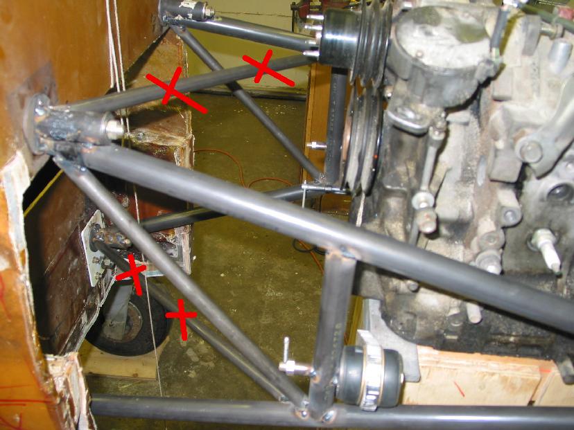
BTW Joe take that diagonal tube just ahead of the slide throttle out
of there. That is a dangerous configuration. It could cause the main motor
mount tube to crack and fail. Stabilize the mount laterally with
a ball jointed strut to the wing strake.
Paul Lamar
Thanks Paul,
That diagonal member is coming out to make room for the Spintech muffler
that is going there.
Joe
Remove both the upper and lowers.
If you don't have room for a ball joint link from the aft rubber bushing area
tie the motor mount to the lower cowl with a bolt. Also use 10-32 screws to
hold on the front part of the lower cowl. That will be all you need as
there is little side load on the motor mount. It just needs to be stabilized
from vibration. The reason we put the rubber bushings near the bottom
of the engine using a Schertz beam is so we can get some diagonals under the oil pan.
Paul Lamar
--
The Rotary Engine NewsLetter. Powered by Linux.
ACRE NL web site.
http://www.rotaryeng.net
Youtube key word UTUBPLEASE
Copyright 1998-2009 All world wide rights reserved.