-------- Original Message --------
Subject: Intake manifolds
Date: Fri, 22 Jan 1999 03:12:06 -0800
From: Paul <
rotaryeng@earthlink.net
To: z <
rotaryeng@earthlink.net
Paul Yaw wrote:
Hi everybody,
I would like to point out a few things concerning intake tuning that I
think are inaccurate, and expand on a few others.
For some reason that I cannot explain, whenever I verbally disagree with
someone I tend to feel that I am being argumentative and abrasive. As a
result, I normally keep my mouth shut if I disagree with someones
opinion. Because of that weird personality quirk, I had not intended to
respond to this. Then it occurred to me that I certainly wasn't doing
anyone a favor since the whole point of this mailing list is the
exchange of ideas. So here goes.
Tracy Crook wrote:
I think we must remember there are two different methods of tuning at work
here.
The tuned pipe manifold that has been the major topic of discussion on this
thread depends almost entirely on inertial effects
A "tuned pipe" refers to using the naturally occurring organ pipe
resonance to "supercharge" the engine. Inertial supercharging is an
entirely different matter, but both methods rely on increasing the
pressure at the intake port during the period from bottom dead center to
intake port closing.(Approximately 70 degrees after bottom dead center
on a 6-port 13B) The purpose is to create a pressure differential
between the intake port, and the chamber so that the chamber will
continue to fill even though its volume is decreasing.
(once the air starts
moving in the pipe it wants to stay in motion) and the resonant frequency of
the pipe. (major simplification here) This is certainly a legitimate method
of increasing volumetric efficiency but it has certain drawbacks. One is
that the improvement works over a small range of engine speeds (and as has
been pointed out, actually hurts at others) and the pipe length is rather
long at the engine speeds we want in aircraft use.
Regardless of the length of a pipe, these pressure waves will ALWAYS
exist. However, the pressure waves will typically be stronger in a
longer pipe of the same diameter. The reason for this is that upon port
opening the mixture in the intake pipe must be accelerated to initiate
flow. A longer pipe has a greater mass of mixture to be accelerated,
and so will require more energy to do so. This results in a stronger
initial pressure drop in the chamber which is what initiates the
pressure wave in the first place. In the case where the pressure wave
is initiated by the pressure increase after intake valve closing, the
same thing applies. The greater mass of mixture results in a higher
pressure which of course initiates a stronger pressure wave. Mazda, in
their SAE paper concerning the "Dynamic Chamber" completely ignores the
effect of the initial low pressure wave initiated at intake port
opening. Using long pipes for the purpose of harnessing high amplitude
pressure waves will most certainly have the effect of lessening the
power at some speeds, and increasing it at others.
The other method (the one I designed around) is the "Dynamic Chamber"
effect as described in Kenichi Yamamoto's book. I reprinted the charts
showing how this worked at the end of my conversion manual. The full
explanation of this effect would require a much longer message than this but
if you study and understand what is going on here, you will see that it
depends on the fortuitous timing between the two rotors in the 13B. (note
that this will NOT work on a three rotor 20B due to the different timing
relationships between rotors). One really nice thing about it is that it
is a broad band effect. It works at ALL engine speeds and has none of the
"dead spots" of the tuned pipe.
The "Dynamic Chamber" effect also relies on pressure waves traveling at
the speed of sound. For this reason it will be "in tune" at some speeds
and "out of tune" at others just like the pressure waves in an
independent runner manifold. The purpose is to have the pressure waves
arrive at the intake port at the proper time. Since the speed of sound
does not increase with engine speed, this can only happen over a very
narrow rpm range. If you look at SAE paper 831010 you can see that the
engine actually had better volumetric efficiency at 3000 rpm with a
separator in the plenum which kept each rotors pressure waves separate
from each other.
snip......... More stuff from Tracy.
In last months tech. article I went into a fair amount of detail on
pressure wave tuning. As it is written, it is meant to be applied to
the exhaust system, but pressure wave theory applies to intake and
exhaust in the same manner. You can find the article at
http://personal.riverusers.com/~yawpower/jantech.html
Good explanation of tuning effects Paul.
Thanks.
BTW what is the title of SAE paper 831010?
The proof of the various theories will be discovered in the long
run with actual performance of airplanes.
I might point out we don't give a fig about how broad the torque
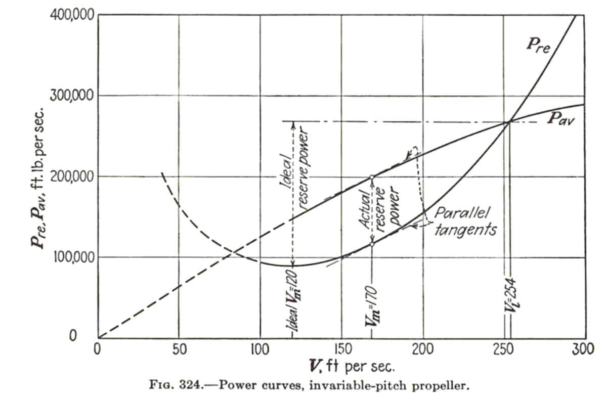
curve is. The chart below is from Theory of Flight the classic
book by Von Mises. Pre is power required and Pav is power avialable.
Pav is mostly a function of the propellor. A variable pitch prop
or constant RPM prop (constant max HP) would convert the Pav to
almost a horzontal line. This chart is for a fixed pitch prop.
Paul Lamar
The Aircraft Rotary Engine Newsletter. Powered by Linux.
http://home.earthlink.net/~rotaryeng/ http://www.linux.org
===============================================================================
LAST 8 years later :)
==============================================================================
------- Original Message --------
Subject: 13B intake
Date: Tue, 19 Jun 2007 10:39:51 -0700
From: Rotary Engine
<rotaryeng@earthlink.net>
To: AARotary Engine
<rotaryeng@earthlink.net>
Paul,
Okay, I can't stand it! I have a beautiful airplane almost ready to fly
and I don't want to skimp on the power plant. I ordered what I think I
need to build the runners and dynamic chamber, but now I'm not sure it
will all fit under the cowl. How important are size and shape of the
chamber? and I am shooting for 28inches on the runners right? How about
the significance of where I install the injectors?
Sorry I'm a pest!
Steve Denny
No problem Steve. I'll work with you until you have something you like.
Thats is why I am here.
Forget the dynamic chamber. The runners would have to be only 12 inches
long
as that is probably very difficult to convert to actual hard ware.
The Mazda versions are designed for torque at 3000 RPM which is useless
in an aircraft. Use some 2 inch OD tubes on the outer ports
and 1-3/4 OD or 1-7/8 OD on the two center housing ports. Make
them about 28 inches long but design it so you can change the length
a few inches one way or the other. Put a plenum on the end.
If you use a 4 inch round tube plenum and weld the runners in you get
a fair transition so you may not need trumpet mouths on the
ends of tubes where they enter the plenum. Your throttle body
looks fine. Cold ram air is very important. However if you
have a dusty runway you will need a filter some place.
The injectors can go anywhere. There has been reported a slight
BSFC advantage if the injectors are mounted out near the plenum.
Others say no.... mount them close to the engine.
This Ford Escort manifold is the right idea but the runners
are too small.
Put a power bulge on the cowl if necessary :)
Paul Lamar ...No rotor no motor.
Paul,
Oops! Sorry I fat fingered the keys and sent that last one by mistake.
Thanks for the info. It sounds easy enough. I plan to use thin wall 4130
so I can weld it. I'm not sure what to use or where to look for the 4".
Should the pressure taps and temp sensor for the controller be mounted
in the plenum then?
Steve
Yes on mounting the pressure tap and temp sensor on the plenum.
BTW you might want to run it the way it is. I am sure you will
get at least 150 HP. Later on after you fly it you can make
some improvements in engine HP.
--
Paul Lamar ...No rotor no motor.
The Rotary Engine NewsLetter. Powered by Linux.
ACRE NL web site.
http://www.rotaryeng.net
Copyright 1998-2006 All world wide rights reserved.
--
The Rotary Engine NewsLetter. Powered by Linux.
ACRE NL web site.
http://www.rotaryeng.net
Youtube key word UTUBPLEASE
Copyright 1998-2009 All world wide rights reserved.