05/09/2009 01:35 PM
Paul,
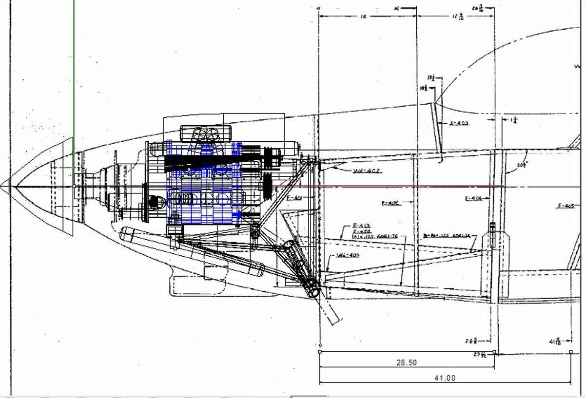
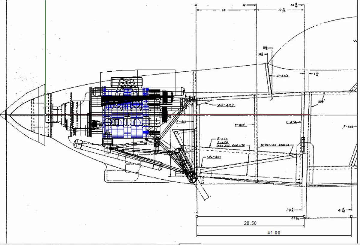
I am in the process of trying to stuff (on paper) everything under the cowl
on my RV-4. Two and two doesn't seem to come out four. Could you supply
me with the following correct dimensions for the Renesis 2005 engine.
1) Is the horizontal center line of the crankshaft located directly
above the center line of the crankcase holes?
2) What is the distance from the center line of the crankcase to
the base of the block where the oil pan attaches?
3) How much, in degrees, should the engine be offset to compensate
for torque on takeoff? Where is it measured from? The firewall?
The rear of the engine? And how much does that move the propeller
shaft over at the very front of the cowl?
Thanks!
Gene
I am not sure I understand question one. I assume that is the case but why would
you ask? To what accuracy are you referring? I would say it is within .001 inches.
Second question. See the attached dwgs. If you need cad versions let me know.
Question three is the same as Vans recommends as long as you are using Tracy's
2.85:1 gear box.
Here are a few installation suggestions.
Also see
http://www.rotaryeng.net
If you are using a symmetrical cowl with Vans off sets let me know
and I can tell you where on the firewall the center line will intersect.
If you are using a stock cowl with Vans off sets I'll need an accurate
dwg of the stock cowl which I don't have. Vans dwgs should have that info.
Jerry Hey can build a motor mount with any off set for you as his jig
is set up to do that automatically. <
jerry@jerryhey.com
Paul Lamar
I do have Van's new beautiful, very expensive cowl and I have Jerry's excellently
welded engine mount. That is my problem, the two are not compatible.
1) There is a drastic interference with the forward legs(?) of the engine
mount and the bottom/side of the cowl.
2) The offset of Jerry's mount is a lot larger than that of the cowl.
3) The front of the cowl is not parallel with the base of the spinner.
4) Jerry's mount has an upthrust of about 1/4" from the rear of the engine
to the front of the engine. Is this right? I can shim the rear end
rubber mount if it is not correct.
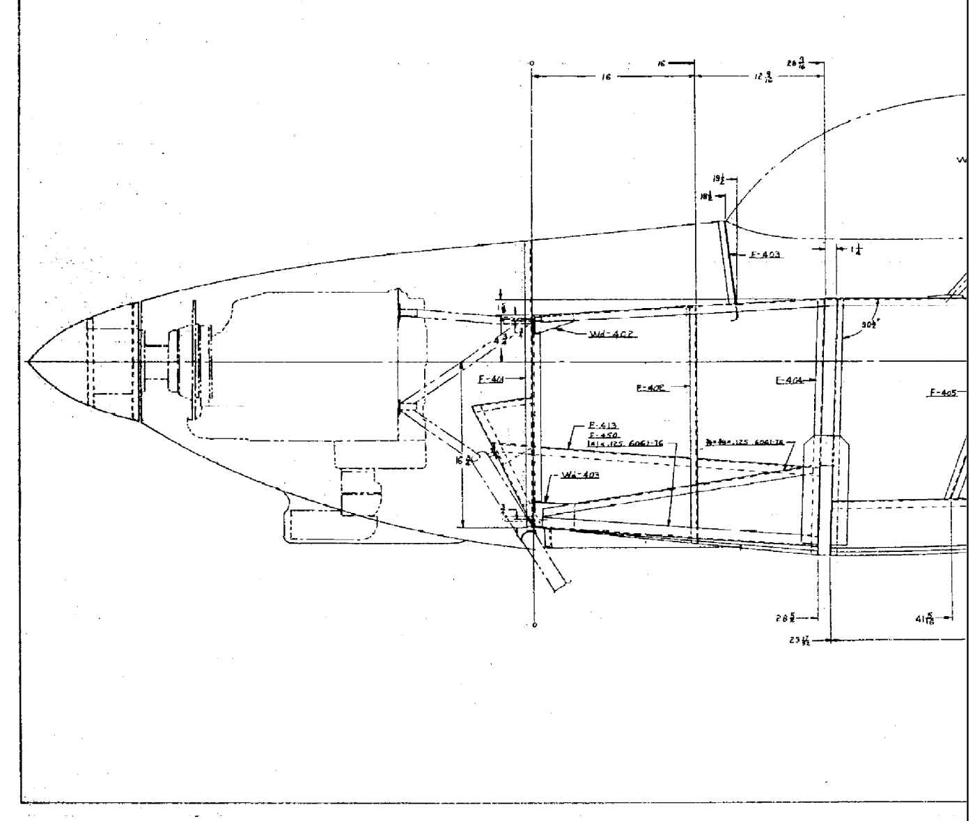
After kicking this around for quite a while, I scaled Van's drawing.
(He is a little shy on dimensions.) The length of the cowl comes out
to be 38 1/2". The length of the fiber glass cowl is 36", and if it
is cocked to match the mount it would effectively be only 35" on the
left side.
To test this out, I set the cowl vertically on a table and propped
it up 3 1/2" on the left side and 2 1/2" on the right side, and put
the mount inside. By eyeballing it, it looks close. The front legs
of the mount needs to be trimmed about 1/2". The nose of the cowl is
another matter. They lengthened the left side in relation to the right
side. Had they left it alone it would be about right.
I am wide open for suggestions as to what to do now. Perhaps I
should just scrap the whole project, RV-4 and all, and get on with my life.
Gene Sandburg
-----------------------------------------------------------------
Got any pictures Gene? Don't panic almost anything can be fixed.
Are you saying the mount is too long for Vans cowl?
Why 3.5 inches on one side and only 2.5 inches on the other
side? Did you give Jerry an off set angle and down thrust angle? Did you give
him a distance from the firewall to the prop flange?
Most rotary MMs are 39 inches
so perhaps Vans shortened the Lycoming motor mount and cowl for CG reasons?
did you have these parts before you contracted Jerry to do a mount?
If the cowl is finished you can measure the side thrust angle and the down
thrust angle by using a bubble protractor with the cowl sitting on
a flat floor. You can can also measure the off set with a plum bob.
That is not much of a problem as you can add a couple of inches of fiber
glass at the back of the cowl. A lot of kit plane cowls need to be
trimmed or adjusted by the builder.
The 1/2 inch interference can be fixed with a slight bulge in the cowl skin.
The spinner fit can be fixed with a block of foam and a bit of fiberglass.
The mount shimmed at the firewall to move the prop flange around a bit.
BTW in general everybody. The last thing you want to build is the motor
mount. I said that in the mm article on the web site. Get everything
else first or make a foam mockup of everything else first.
Where are you located Gene?
Paul Lamar
Gene, these are the Van's dwgs I have on the RV4. Is this the same dwg as the
Van's dwgs you have? Is the cowl you have significantly shorter than these dwgs
would indicate?
Jerry has built several RV4 mounts in the last 11 years with no complaints.
Paul Lamar
The Rotary Engine NewsLetter. Powered by Linux.
ACRE NL web site.
http://www.rotaryeng.net
Youtube key word UTUBPLEASE
Copyright 1998-2009 All world wide rights reserved.