The next step after the 555 fuel injection system is a good ignition
system.
I have come up with a very simple way to have four or more sparks
one every 15 or 20 degrees or so of the e-shaft. I think this might
reduce the BSFC by about .03 or .02 at least I hope it will.
Patent applied for.
That does not sound like much but it is about
5% reduction in fuel burn. Mazda completely redesigned the 16B rotary
and retooled the factory to get a 5% reduction in fuel burn at
car power levels. Cost? Hundreds of millions if not a billion dollars.
http://www.rotaryeng.net/pat20090101103.pdf
Most of this was optimizing the position of the spark plugs
and the timing. Evidence that there is potential for lower
rotary engine fuel burn with more R&D focused on the ignition system.
In our case we have a moving combustion chamber where the fire
travels along side the spark plugs for quite some time. IMHO We want
the spark plugs to continue to fire for as long as the unburned
and burning mixture is still present moving past the plugs. That takes
8.3 ms at six thousand RPM cruise RPM. See chart 2.
A capacitor discharge ignition system is very good at firing
spark plugs fouled with 100 LL but it only fires for .2 ms. Even
an inductive system (Chevy LS1 coil) or stock Mazda ignition
only fires for about .8 ms.
IMHO NO WHERE LONG ENOUGH FOR WHAT WE NEED!
IMHO we need an ignition system to fire for many milliseconds or
at least 60 e-shaft degrees.
This is why I am doing a m.s.d. ignition system with several pre-charged
capacitors fired in rapid sequence by a by 3 or 4 inductive sensors
per rotor mounted 15 or 20 degrees apart near the e-shaft ignition steel
disk with one tooth. Extremely simple and no computer required.
I hope this is a break through in improving the BSFC of
the rotary engine. I think it is worth a try.
MSD makes a multiple spark capacitor
discharge ignition system widely used by Mazda rotary
engine racers but it only works up to 3000 RPM. After that it
is "one strong spark" says MSD. Not enough IMHO.
I called AEM and it does not fire
more than once past 3000 RPM according to the electronic
tech guy. He kept saying there was not enough time
but he was incorrect about that. I don't think they
designed it for a rotary where the rotor is moving one
third as fast as the shaft.
Here are a few charts from Heinz Heislers book Advanced Engine
Tech and others. The first chart shows that; as the fuel air
ratio gets real lean and the pressure lowers in the combustion
chamber at high altitude the voltage required to fire the plugs
goes up.
Klaus has exploited this situation to lean his engine
out at high altitude and improve the BSFC to remarkable levels
by increasing the spark voltage. He has achieved as much as 100
MPG at 130 MPH and 60 MPG at more reasonable cruising speeds.
This is a piston engine where the spark plugs are at one end of
the fire and the piston is at the other end unlike our
situation. IMHO much of the piston engine ignition knowledge
is not applicable to the rotary.
P1080482 through P1080487 are the range of rotor positions I
intend repeatedly firing the spark plug. Mostly the leading plug
(lower plug) as one does not want to risk igniting the mixture
in the following chamber. In other words we are going to chase
the fuel air mixture with the spark.
I have searched high and low for a long time for a LOW COST high
power 12 volt to 300 volt DC to DC converter. Finally I found the
solution. Here is what I have come up with. See DC-AC 1 through
3.
This is a mass produced under $100 automotive DC to 110
volt AC 750 watt fan cooled converter. It weighs about 2 pounds.
All I need on the output is a full wave diode bridge circuit
to convert it to about 250 volts DC for rapidly charging the
capacitors. One for each spark. Current to the capacitors can be
as much as 3 amps! At the full 750 watts current drain on the battery
will be as much as 60 amps! I am not sure I need this much ignition power
until I test the overall system at 7500 RPM but I have it if I need it.
More info later on the total system.
--------------------------------------------------------------------------------------
You are looking at one of the most powerful ignition systems ever put
on an engine and it only cost $35 :)
This is the PC board of the XO Vision 380 watt 110 volt Ac inverter.
750 Watts peaks. Fortunately XO Vision did not go to all the trouble
of forming a perfect sine wave. This modified square wave is perfect
for my purposed as I will invert the lower half with a bridge rectifier.
It put out 320 volts peak to peak so when inverted it will be 160 volts
DC. That is the big trick that allows me to use a mass produced off the shelf
item as a powerful CD ignition system. The current drain on the 12 volt
bench power supply was 8 amps. The load was a 60 watt incandescent light bulb.
The unit does not like to run with no load.
The scope horizontal was set to 2 ms per division and the vertical was 40
volts per division so you are looking at 320 volts peak to peak. After the
bridge rectifier is installed it will be 160 volts DC more or less.
I have located a higher quality, more expensive 400 watt inverter unit
that puts out European 220 volts AC so the DC voltage should be around double
this or about 320 volts. Just about right for a CD ignition system. More
to come as we will need caps and switches.
Paul Lamar
--
Paul,
VERY INTERESTING. Good Idea. Multi-caps, multi-strike leading plugs.
Don't understand why you would need multiple sensors or the wheel
though. The computer knows the rpm and hence the firing window and
spacing of the four sparks. Yep thinking MegaSquirt again but perhaps
you can do it without a microprocessor. The big challenge will be
finding a power supply that will live a long long life. Ozone
generators and yes off- grid inverters come to mind. Careful on the
cheap units with the high rating. The $100 dollar shown is made in
China and the 750watt is PEAK momentary rating. Most that size are
lucky to output 250 watts continously. If made in China the FETs will
burn out in several months. I have stacks of them in the warehouse
before I learn to buy industrial quality units.
What size capacitor are you considering?
Doug in Japan.
We don't need no stinking computer :)
The computer is replaced by 10 crank angle sensors.
Highly redundant. Eight for ignition triggers and
two for 555 injection triggers. Software to trigger ignition
capacitors every 20 degrees at all RPMs would be a nightmare any
way.
I figure I will try 2 Mfd. I know 1 Mfd works as I used them in
a Heath Kit CD system 50 years ago. The HK 300 volt power supply
was done by a mechanical reed vibrator and a transformer.
This inverter is dangerous with several hundred volts and lots of
current to fry your ass.
Don't fool with this nude inverter at home!
EVER!.
We are professionals!
We know what we are doing :)
----------------------------------------------------------------------
OK guys I updated the web site so new people can catch up on this subject.
http://www.rotaryeng.net/Why-CDI.html
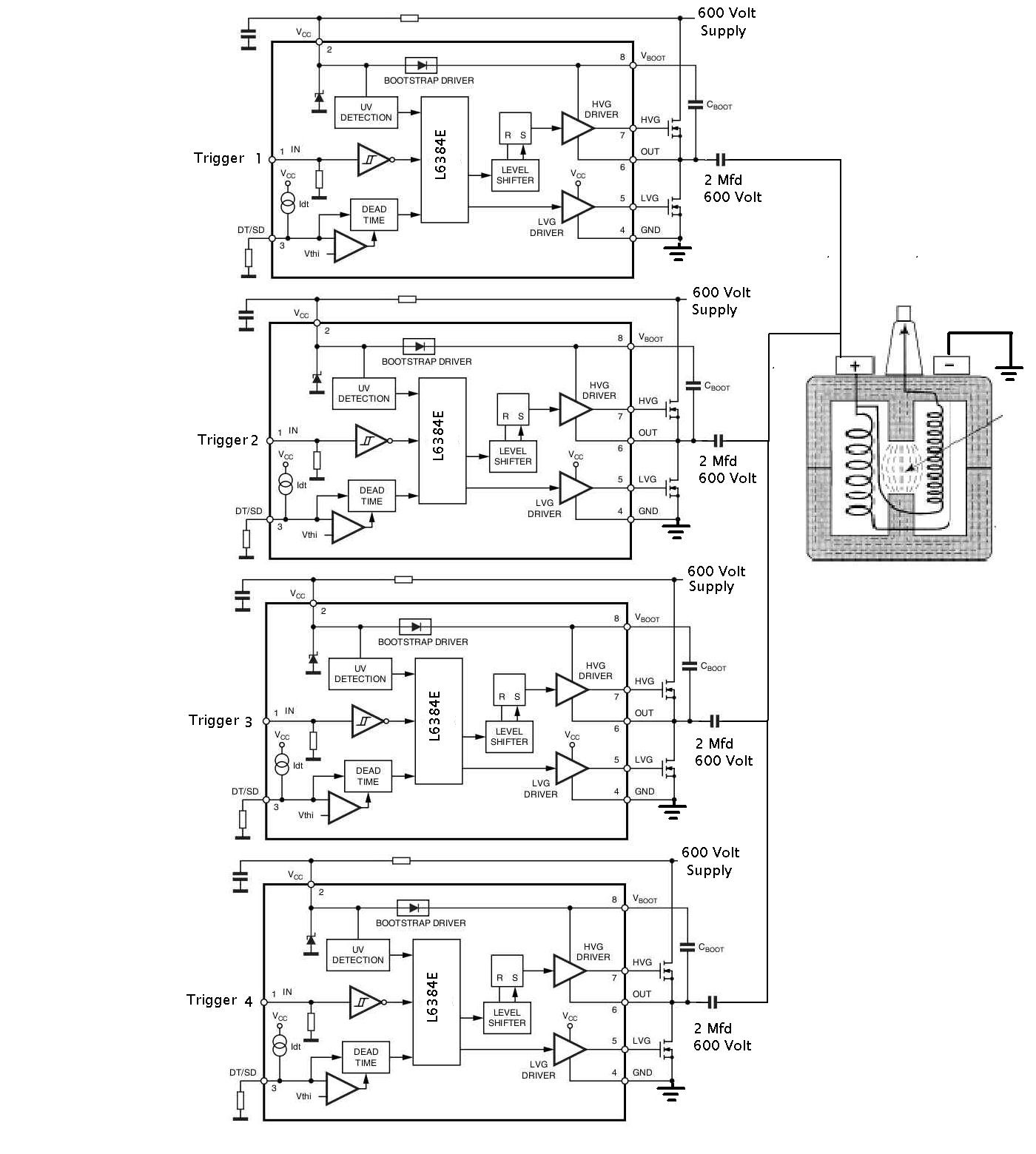
Here is the preliminary coil driver circuit.
These circuits act like double pole solid state switches. When the trigger comes
in from one of the crank angle sensors the circuit disconnects the main
high voltage power supply and dumps the charged 2 Mfd capacitor through
the stock Mazda ignition coil. Then it closes again to recharge
the capacitor for the next time. These driver chips used are about a buck each.
Not including the cost of the FET's of course.
Take a look at it and see if you see something that will not work.
Paul Lamar
--
The Rotary Engine NewsLetter. Powered by Linux.
ACRE NL web site.
http://www.rotaryeng.net
Youtube key word UTUBPLEASE
Copyright 1998-2009 All world wide rights reserved.