Paul,
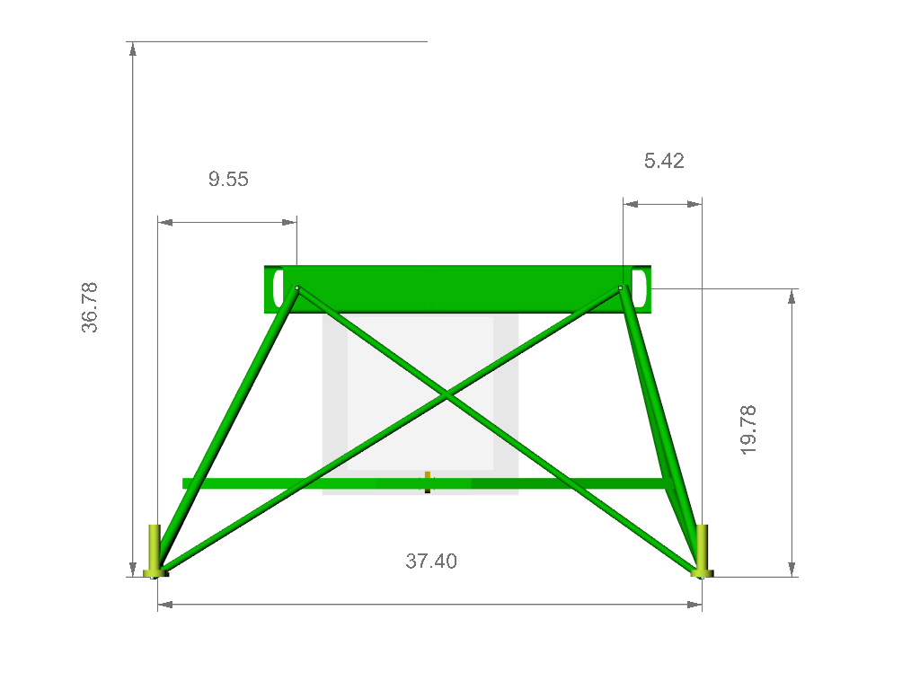
All the X & Y dimensions are from the flat firewall.
Note there are five mounting points. Designer call for up
to
180hp with the four point, with up to 260hp with five
points.
I'm trying to get an idea of the room using either a 13B
or
20B. Only one Bearhawk is flying (Elden Yates). Little
details, but Elden ended up putting his battery next to
the
PSRU to get some weight out on the nose!
Plan is to use Tracy Cooks PSRU. With 180hp,
Bearhawk
cruise is 140mph, with 260hp it is at 160 mph (75% on
both
numbers).
--Tom
There are five mounting points on the Bearhawk Firewall.
Firewall is
approximately 2" larger at all mounting points.
In Inches:
XY
Lower Left3.500
0.000referenceLower Right
31.1880.000
Upper Left
0.00020.188
Upper Right
34.68820.188
Upper Middle
17.34424.844
THRUST LINE
17.34415.844Firewall
set back at 6 degrees (top towards tail).
Prop Flange (front edge) to
VERTICAL MOUNT -
40.625"Note, from firewall (6
degree lean back - top towards tail)
is sin 6 *
(Thrust Y position) or an additional
1.656"
-- end of email ---
Does this look right?
Now you want me to lay it back 6 degrees?
Paul Lamar
Paul,
The bottom measurement should be changed from 27.500 to
27.688"
Upper middle is 24.844" from the lowest two holes.
Correct, rotate the firewall back 6 degrees. Point of
rotation is from
the lowest two points on the firewall.
Thank You,
Tom
OK Tom Here it is.
Paul Lamar
Looks good.
Bob Barrows, the designer, doesn't have an email account! No
computer,
either! I suspect that is why he gets so much done.
Thanks,
Tom
I'll see Bob at OSH and show him some of this stuff.
Here are some preliminary 3Ds. Ask questions if you see something
that looks strange. Upper motor mount is not in yet but we
will use a rubber ball jointed strut mount to above the water pump.
Are you using an RX8 engine? That area differs from the 13B.
Paul Lamar
Paul, am I interpreting the 6 degrees incorrectly...that the mount
has 6
degrees of upthrust? Also, related question, on your mount design
that
Jerry has been welding, is the prop flange 90 degrees vertical?
Steve Beckham
No the BearHawk firewall is laid back six degrees. This mount has
no down
thrust or side thrust. The down thrust angle can be adjusted
however by
using left and right hand threads on the top strut.
Jerry's jig can accommodate down thrust and side thrust.
For the new guys we have been doing these motor mount designs for
about
the past seven years. A free service of the newsletter.
Paul Lamar
--
The Rotary Engine NewsLetter. Powered by Linux.
ACRE NL web site.
http://www.rotaryeng.net
Youtube key word UTUBPLEASE
Copyright 1998-2009 All world wide rights reserved.
<BearHawk-SF-Dims.jpg
http://finance.groups.yahoo.com/group/BH-PATROL/
Paul, I am impressed with the drawings of the motor mounts and the
completeness of main shapes. In what forms could I pull them into my
Solidworks? And for example, if you extracted a single tube, such as
a brace tube that would have a profile on it, do you have that
profile already done?
I do the work for the Patrol frame and of course that has slightly
different hole placements but I believe the set back angle is the
same...
keep up the good work...I would think this is one of the major
hurdles for going to non-aviation motor. Always good to see the end
result before a dollar is spent.
Scott
Scott- Iron Design L.L.C.
Scott Weinberg
13631 Vail Ave
Clarksville, Iowa 50619
319-276-4400 home/office
319-404-4401 cell/shop/office
scottw@butler-bremer.com
http://www.irondesign-airparts.com/Tailwheels.htm
We have done this in the past using stp format. Here is a RV7 motor
mount in stp format zipped. It is better than iges or dxf. Just un zip
it and import it into Solid Works. It is not always perfect but it is
usually very easy to fix one or two flaws. The jpgs will show you
what it is supposed to look like after being rendered.
I only ask that you check with me first before you make any modifications
as these mounts are subtle and they have been developed and tested for the last
seven or eight years with the help of many people. That includes at least
one crash due to pilot error. I don't want any failures. If somebody changes
it and it fails they are on their own. In general I use .049 wall 4130
tubing tig welded. The beam is available from Jerry Hey. The rubber bushings
can be bought at McMaster Carr and unlike an aircraft rubber mount they
are less than $10. They are made from the same rubber by the same
company that makes aircraft mounts. Namely Barry Controls.
Also read
http://www.rotaryeng.net/motor.html for the design rational.
I am always open for suggestion and improvements as this is the way
the mount evolved in the first place. One of the functions of this
newsletter.
Paul Lamar
--
The Rotary Engine NewsLetter. Powered by Linux.
ACRE NL web site.
http://www.rotaryeng.net
Youtube key word UTUBPLEASE
Copyright 1998-2009 All world wide rights reserved.