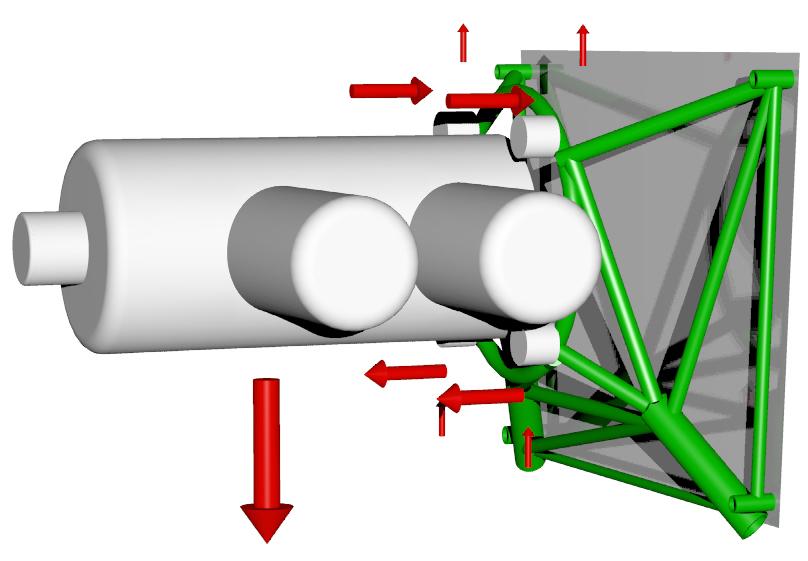
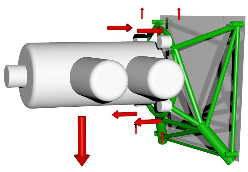
Phillip Groelz is building a cast aluminum front cover incorporating
Lycoming motor mounts much like the Mistral version.
Add some bosses on there Phillipe to mount my ignition
and fuel injection crank angle sensors :)
I talked to Steve Roth who was piloting when the
Mistral Piper Arrow crashed and he said the front cover did not break but
the motor mount was bent. Always good sign. Means the front cover can take
it.
Here are some pictures of the wood patterns and the Mistral version for
comparison. I like the idea that Phillip is using the stock Mazda water
pump
cartridge.
Paul Lamar
------------------------------------
Paul, and Phillip!
Sign me up for a couple (or 3) of those castings! Try and make sure they
fit
all versions of the 13B and 20B's, the 20B larger water pump, have acc
pads
(cs prop pulley driven pump), etc! (I have mostly 13B REW and 20B
engines-the AT engines have a different bolt/starter layout, as does all
the
20B's as they were ALL AT only). In any case.
I suspect that this mount is the typical "dynafocal" Lycoming style used
on
the Lyc O and IO360's like in some of the Piper Arrows If so, I have this
MM hanging from my hangar ceiling. I was waiting for this to
happen.....and
didn't want to deal with Mistral......
Any idea on a price and when
Marc Wiese
Sign me up as well. I'm at least a year behind with doing the same thing.
Had thought of purchasing a complete Mistral engine just for the chance
to measure and CNC that front plate. If it's engineered to handle the
loads of up to and including a 4 rotor you should have no problems
getting customers. Price and timeline would be great.
Greg Fleming
London, Ontario, Canada
Sign me up too if you're taking orders! :-)I have a 20B and would
really like to use this type of mount with my Velocity SE-RG. Any
idea of the weight yet Will the longer tension bolts of the 20B
handle the additional weight thats cantilevered out This would be
a nice piece of work to use with our engines!
Best wishes,
John Bell
Paul, I have been using RX7 and RX8 side housings to measure bolt locations
and water and oil passage interfaces. It looks to me that the tension bolts
thread into the front side housing and do not pass through it to the front
accessory case casting.It looks like the patterns shown will gain some
support from the oil pan attach bolts and water pump studs, however these
are small fasteners and while the oil pan itself appears plenty stiff, the
bolt hole clearance would limit support to the friction component of the pan
and gasket to the front cover. I would suggest looking at some through bolt
bosses that would allow attachment of 1/4" plate brackets back to the core
engine castings. The mounting front cover mounting idea should advance
rotary use as Lycoming mounts are available for most anything, and the motor
mount worries builders more than the induction system which you have already
taken the pain out of. How does the center of gravity of the
rotary/redrive/prop compare with the Lycoming engine an prop assuming the
cooling system is under the engine? george grimes
The center of gravity will be well forward of the Lycoming. I was concerned
with the same thing and that is why I checked with Steve Roth of Mistral.
If it survives a crash it is probably strong enough.
The two hollow dowel pins would help locate the motor-mount/front-cover.
The oil pan flange will help out as you mentioned.
Seems to me is the most highly stressed part of the new front cover is the
upper right corner with few six mm bolts in that location. Mistral has added
at least one new 6 mm screw in that area. High strength bolts are used.
Paul Lamar
Is this cover meant to fit the larger 20B (and 13B REW) oil pump
configurations? Those engines have uprated oil pumps.
Marc Wiese
Paul
"Seems to me is the most highly stressed part of the new front cover is
the
upper right corner with few six mm bolts in that location. Mistral has
added at least one new 6 mm screw in that area. High strength bolts are
used."
I agree. Mistral's work is well done. And yes CNC would be stronger
and lighter. Also a point to note is their front cover is attached to
iron. When using an aluminium front housing things might get, uhhh,
interesting with the CG so far away. The lower mounts are in compression
and shouldn't be a problem for the amount of metal they have. The
upper ones concern me but not in regards to the front cover per se. If
one could bring that load forward near the bell housing interface it
would be a lot safer. This would keep the engine block in compression
instead of stretching it and turning it into part of a long lever in
which the internal dowel pins are creating localized stresses. The
engine bolts aren't that strong and depend on sharing the loads equally
between them.We are playing with an engine that is segmented axially
compared to one split down the middle. The superior strength of the
Lycoming case should be obvious. I suspect that this was one reason
Mazda abandoned the front case mount and went to the trouble to put
close to the engine CG. and attached to the intermediate housing. If one
has the cowl space then their are only two words to remember with engine
mounts.BED MOUNT. It is the superior and safe solution and how Mazda
envisioned the engine to be mounted. One may say, "Yes but I am making
an airplan...." Yes but you are, but you are choosing to fly with an
engine engineered to be supported in a different manner.
Doug in Japan
If the CG of the 3 rotor is 2 feet ahead of the front cover
and the total weight is 400 pounds the bending moment
at the rubber bushings is 4,800 foot pounds at 6 G. The tensile
load on the upper rubber bushings is therefor about 4,000 pounds or
2000 pounds each bushing. The compression load on the lower
bushings is the same. I am sure the rubber bushing will take
a momentary load of 1000 pounds. The 1/2 inch bolts running
through the rubber bushings would be no problem. Just about
any half decent 1/2 inch bolt will take 30,000 pounds.
The upper 10 mm (a little over 3/8th inch) tension bolts
may be over loaded however as they already have a tensile
stress in them due to just torquing them down. Over all
it looks a little marginal but it might be OK.
A metal constant speed prop is 50 pounds all by itself
so it is probably not a good idea.
The shear stress must be taken by the two hollow dowel
pins that run through the housings locating them relative
to each other. They will probably survive.
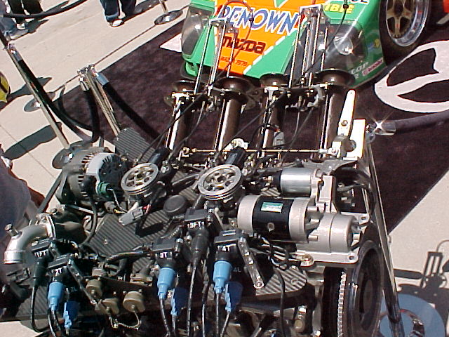
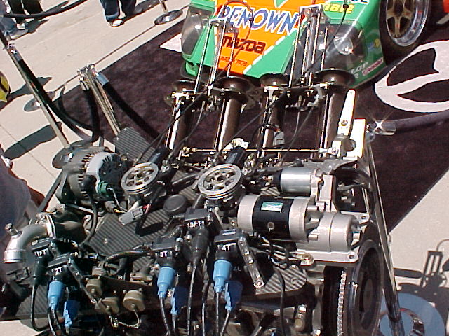
In the stressed Lemans engine Mazda added upper and lower plates
on the engine to take the bending loads. You can clearly see it
in this 2nd picture and the mounting bolt holes. It appears
to be carbon fiber honeycomb. Much like an I beam.
Paul Lamar
The Rotary Engine NewsLetter. Powered by Linux.
ACRE NL web site.
http://www.rotaryeng.net
Youtube key word UTUBPLEASE
Copyright 1998-2009 All world wide rights reserved.