Paul
It appear torque can be measured with proximity sensors as well. Two
sensors.

 "Proximity and displacement sensors also can detect torque by
measuring the angular displacement between a shaft's two ends. By
fixing two identical toothed wheels to the shaft at some distance apart,
the angular displacement caused by the torque can be measured. Proximity
sensors or photocells located at each toothed wheel produce output
voltages whose phase difference increases as the torque twists the
shaft. 
 Another approach is to aim a single photocell through
both sets of toothed wheels. As torque rises and causes one wheel to
overlap the other, the amount of light reaching the photocell is
reduced. Displacements caused by torque can also be detected by other
optical, inductive, capacitive, and potentiometric sensors. For example,
a capacitance-type torque sensor can measure the change in capacitance
that occurs when torque causes the gap between two capacitance plates to
vary.
http://www.omega.com/Literature/Transactions/volume3/force3.html
Doug in Japan
The hall effect sensor is ideal for that as it turns on and off
in one or two micro seconds. One on the front of the engine
and another on the rear can measure torque using a high speed
micro computer. In effect what happens is you are measuring the
slight twist in the e-shaft.
BTW I got the bench test ignition system up to ten thousand RPM using a
$3 Radio Shack electric motor and a variable voltage power
supply. The RPM can be varied from zero to 10,000 RPM
as the voltage on the motor is varied from zero to 4 volts.
This was tricky to make as the trigger wheel must be pressed on
the .075" shaft. I destroyed a couple of motors before I got
the hole diameter right in the trigger wheel.
I have also given the spark timing a bit more thought. The rotary engine
expansion stroke takes place over 270 degrees of e-shaft rotation.
The capacitor discharge duration is fixed by the ratio of the
inductance of the ignition coil to the capacitance of the charged
capacitor. Typically, from personal experience, using a 2 Mfd capacitor
and a typical spark coil, this duration of the spark is from
about 1/4 millisecond to 1/2 millisecond. At 6000 RPM 360 degrees
takes 10 milliseconds. See the chart.
270 degrees happens in 7.5 milliseconds. Putting it another way
one degree takes .0277 milliseconds to occur. Therefore the hall
effect sensors should be placed about 36 degrees apart to optimize
the system for 6000 RPM. Each spark is then given one millisecond
for the spark to occur before it is shut off and the next
spark occurs. Four sparks starting at 36 degrees before top
dead center at high altitudes and ending at 72 degrees ATDC
should do the trick. Of course these numbers could be varied
but this is my best guess on rotary engine spark timing. At
higher loads the timing would be delayed to something like
first spark at 20 degrees BFTDC, next spark at 16 degrees
AFTDC, then one at 52 degrees, and the final one at 88
degrees. All 36 degrees apart.
I might mention at this point back in the old days
distributors not only advanced the spark as a function of
RPM but also an inverse function of intake manifold pressure.
Since this system has a manual advance for steady state
aircraft use this too can be accomplished.
At higher RPM's there will be less time for the capacitor to
discharge so the degree spacing may have to be adjusted.
Smaller storage capacitors will narrow the pulse at
the expense of lower ignition energy.
A higher voltage power supply is also a possibility but
for now I will stick to the cheap 220 volt inverter.
Smaller magnets can narrow the pulse width from the hall effect
sensor changing the time available for the capacitor to discharge.
A radical idea no matter how you look at it. Far removed
from piston engine ignition technology.
I can use some help on this if somebody has some expertize in electronics.
I have no intention of manufacturing it so that some one could make
some money selling these things to the rotary market if they wished.
I can see how it could help the BSFC particularly in the lower RPM
and lower HP range typical of automotive use. One has a lot more
time to do radical high energy ignition things in those ranges.
I notice watching the RX8 running in the Rolex GT race and judging by
the flames shooting out of the exhaust there is a lot of unburned
fuel coming out of the engine. If burned that would translate
to more power and better MPG.
Paul Lamar
Paul,
I mentioned the exact same idea to you twelve months ago and you poo
pooed it as having no merit to measure the torque across the engine as
it was good for research purposes only. Hence I went to the idea of
measuring the larger displacement between the flex plate and the rubber
isolated PSRU drive plate. The flexplate is attached to pre torqued
e-shaft and the drive plate is attached to the load, in this case the 2%
+ PSRU gear friction losses and the prop air resistance. Measuring
torque across the engine from the drive plate to a front pulley point
wouldn't hurt but I think there would be more potential for
displacement on outer edge of the two plates in the bell housing. It is
easier to set up as well, with one U shape device attached to one of the
flat cover plates on the bell housing.
So if I understand this application correctly it would require two
magnets, and two hall sensors and some sort of logic circuit to poll the
sensors say once every half a second, and then to time and store the
arrival delay of the second signal in a memory buffer as a digital
number. ON time would be measured when the hall sensor voltage reaches
a predetermined high value. OFF time when the voltage reaches a
predetermine low value. The timed event is the duration when the flex
plate magnet triggers an ON event and the following drive plate magnet
triggers an OFF event. What hardware could do this? These events of
course but would be influenced by engine rpm but that relationship
should be a straight curve and can be manipulated by the on board laptop
inside the cockpit. Each event duration value would have to be applied
either to a look-up table, or calculation to come to a sensible Hp value.
Now the small lap top, built into airplane, is for the sole purpose of
monitoring, recording, and displaying engine performance data. Hopefully
I can run it in LINUX though XP might be stable enough. Because of the
abundance of sensors and the twenty foot distance between them and the
laptop I'll need some smart hardware up near the engine and redundant
USB or Rs232 cables providing the connection.
I am not an E.E. so someone please jump in and give me some hard and
software advice as I think a torque meter integrated into a engine
monitoring, system is a 'must have' in a flying dyno scenario.
Doug in Japan
Me poo pooing an idea? Do you have any key words that I can look
up the message. I am getting old and I can't remember that far
back. Probably over 10,000 messages ago :) Perhaps that was before
I found out the turn on time for a Hall Effect sensor was less
than 2 micro seconds.
The hardware could be merely a logic circuit called a set reset
flip flop that puts out a variable pulse width. One sensor sets
it the second one resets it. Integrate the pulse width with a capacitor
and feed the resultant analog voltage into an analog to digital converter.
Subtract an RPM factor.
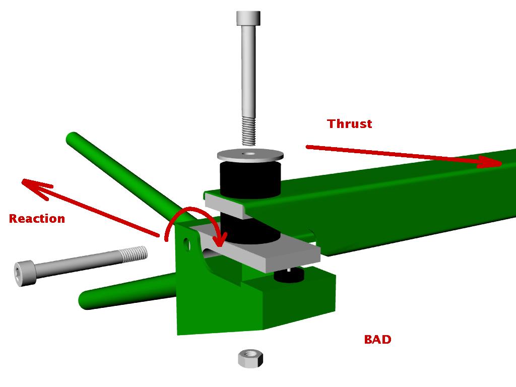
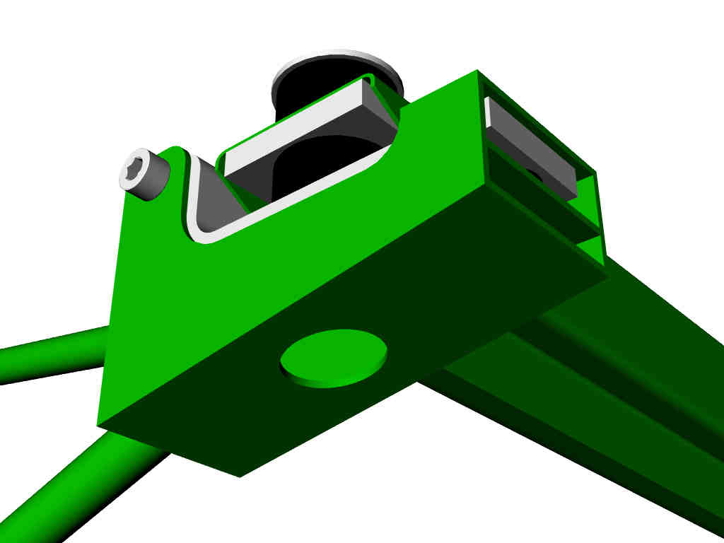
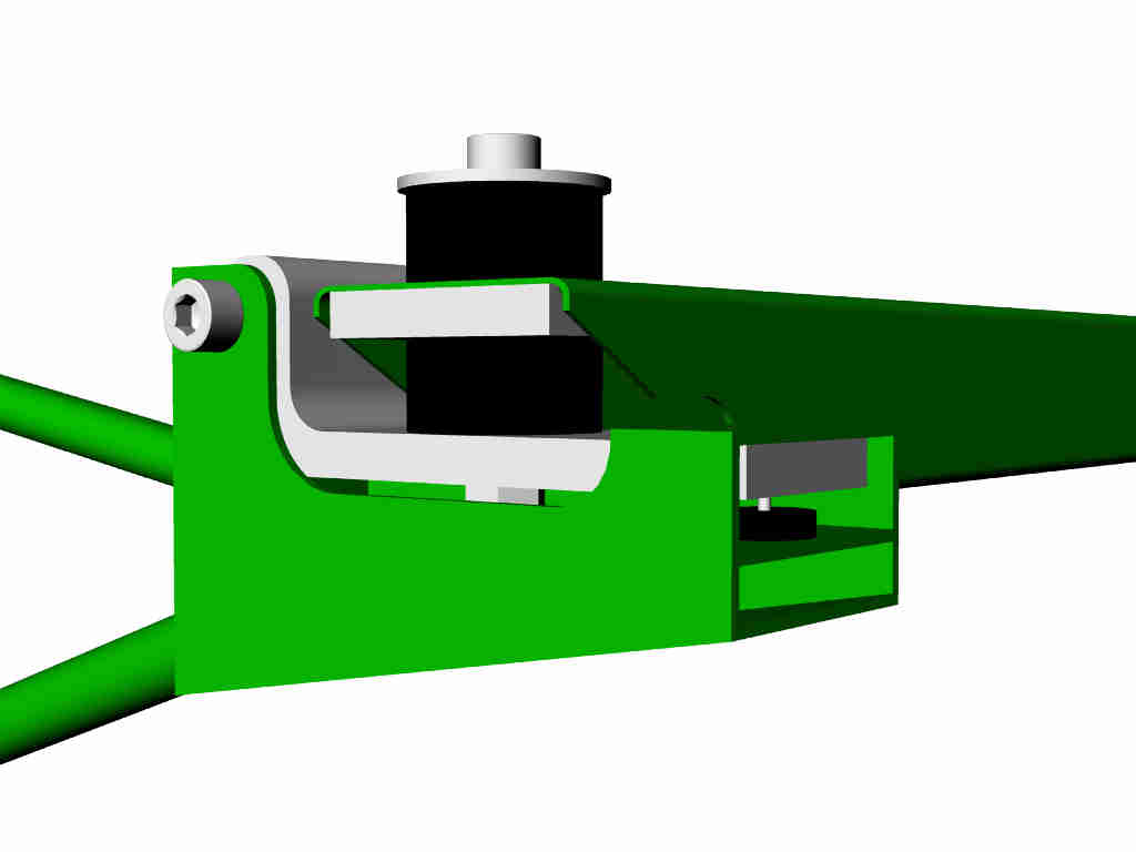
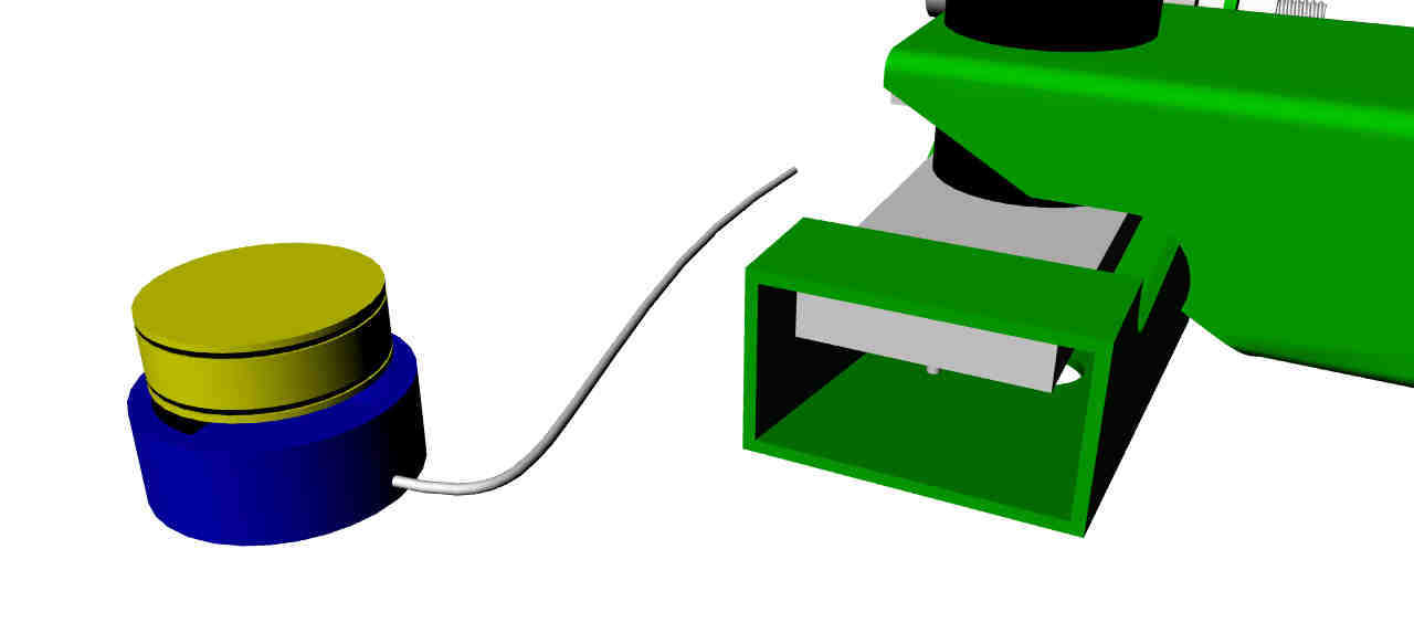
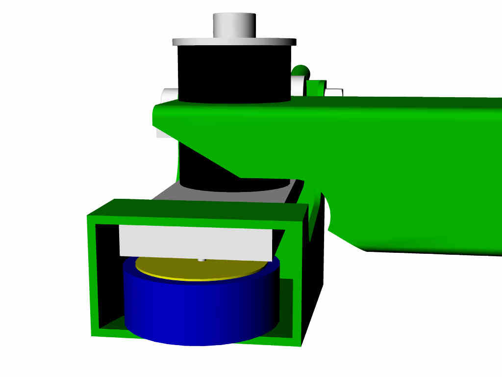
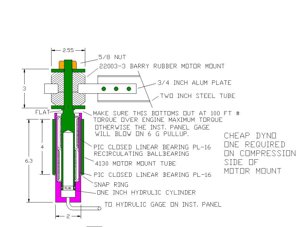
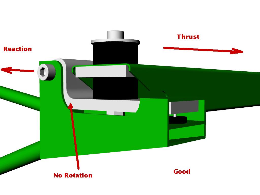
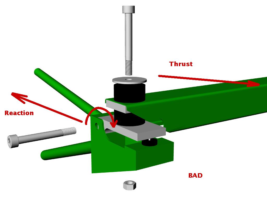
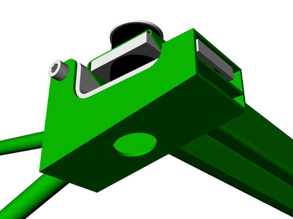
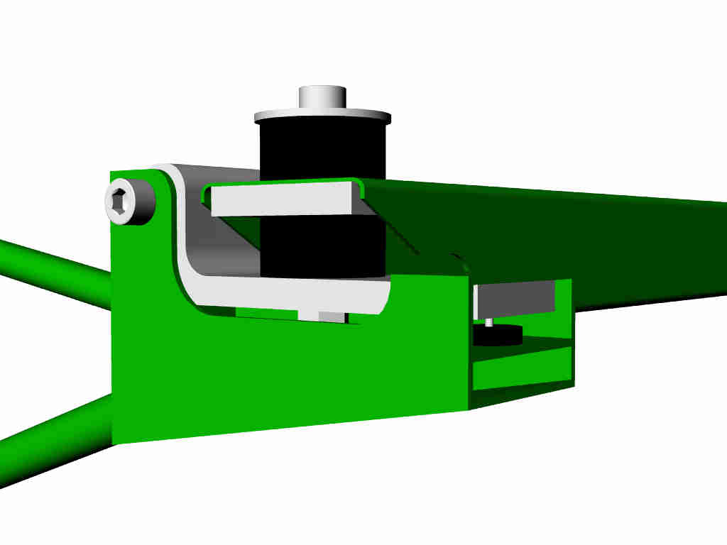
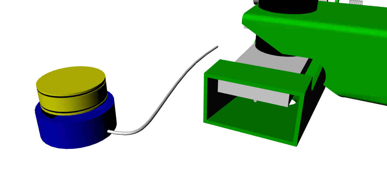
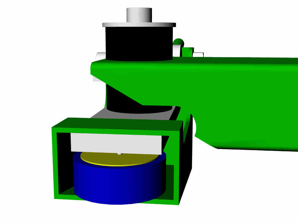
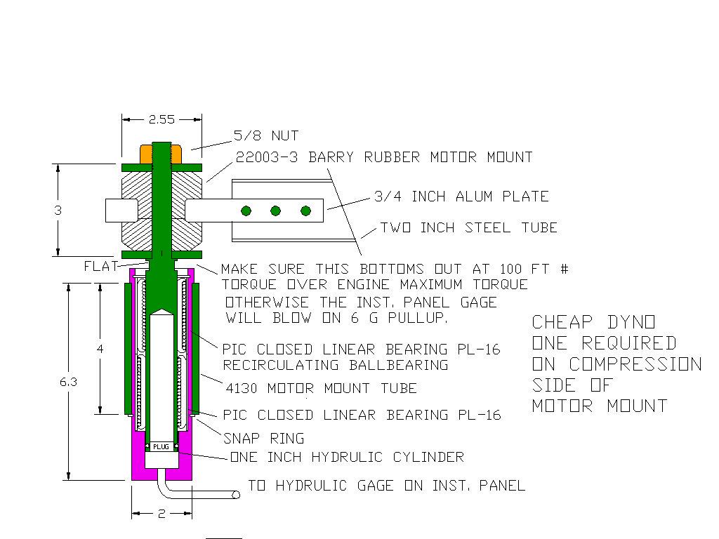
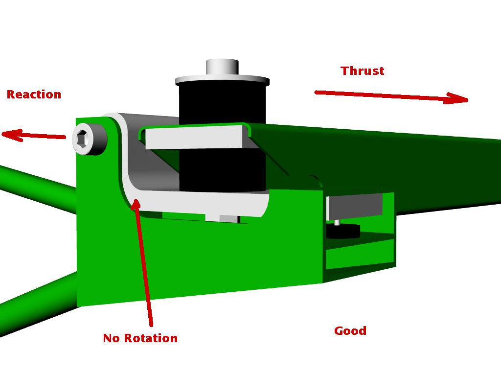
IMHO it is better, more accurate and cheaper just to measure the torque
reaction on the motor mount directly if you don't have helical gears
like the PT6. Also load sensors are getting cheaper with zero to 5 volts
out signal. I guess this is the in the category of poo pooing the idea.
This smells like the conversation we had given all those existing 3D's :)
Paul Lamar
--
The Rotary Engine NewsLetter. Powered by Linux.
ACRE NL web site.
http://www.rotaryeng.net
Youtube key word UTUBPLEASE
Copyright 1998-2009 All world wide rights reserved.