Paul,
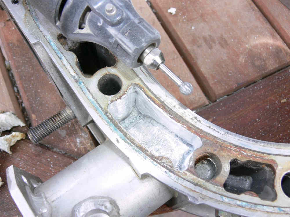
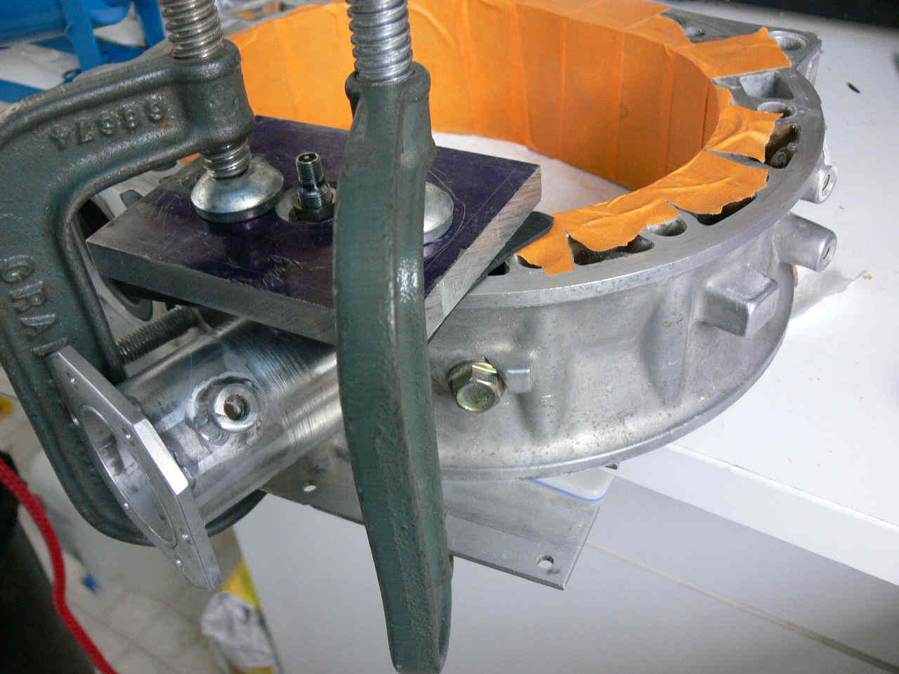
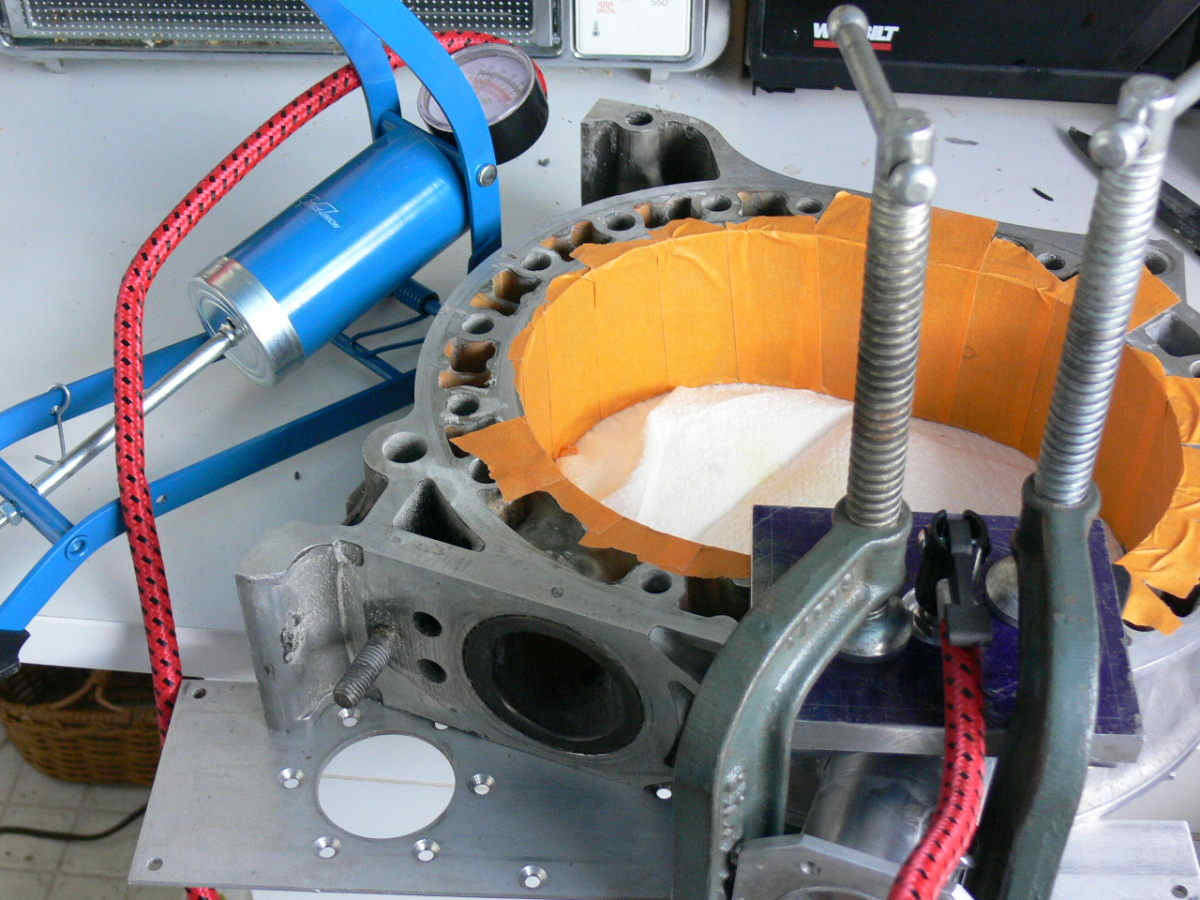
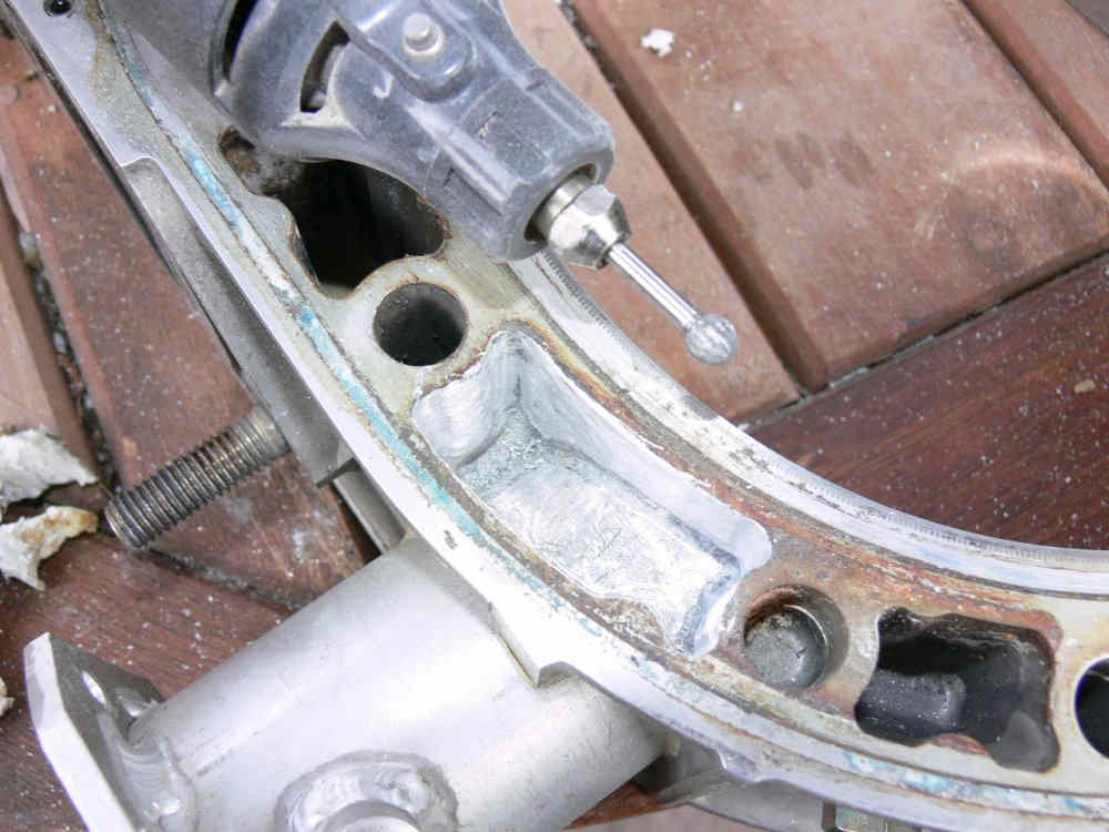
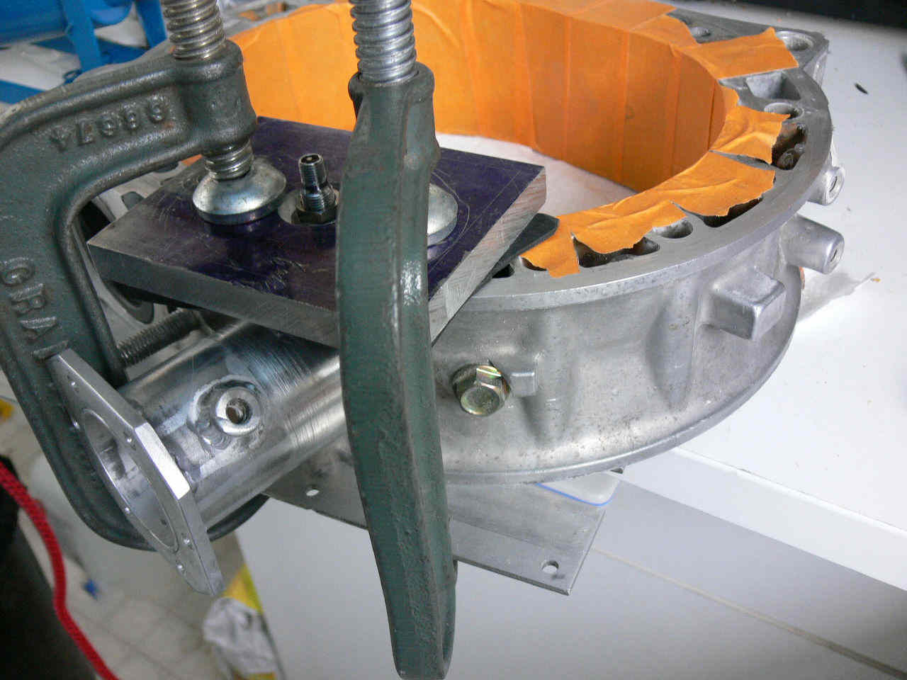
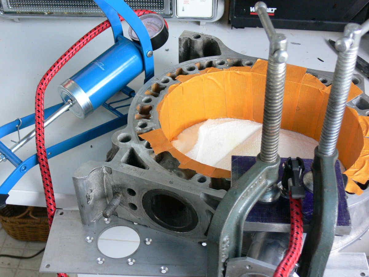
Last week I manage to take some pictures of the jigs
used for making
identical housings based on this cut off test
housing. These jigs
with
positioning dowels and through bolts have evolve to
accept casting
plates for the DEVCON epoxy, or hardened
steel plates with drill
inserts to drill the hold down stud holes for the
throttle. Ditto a
plate to drill the fuel injector bore holes
and the injector hold
down
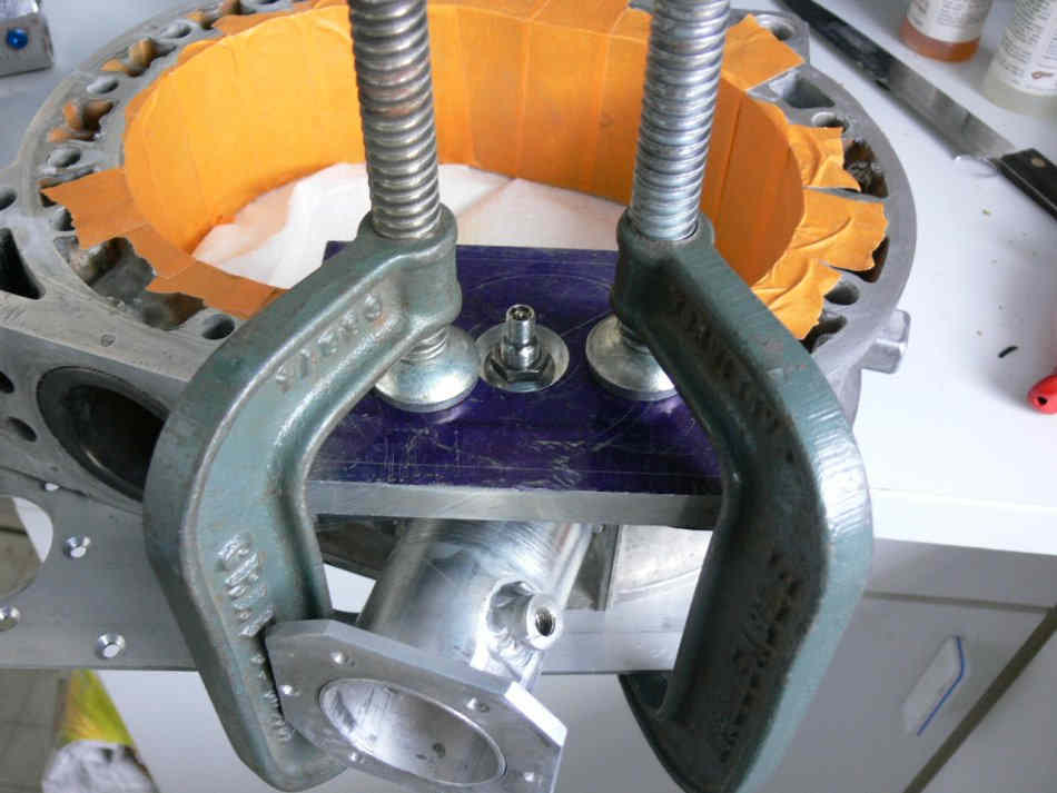
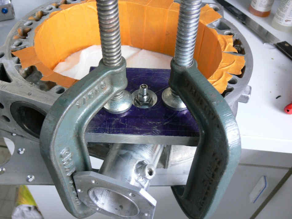
plate studs. As of today these jigs also
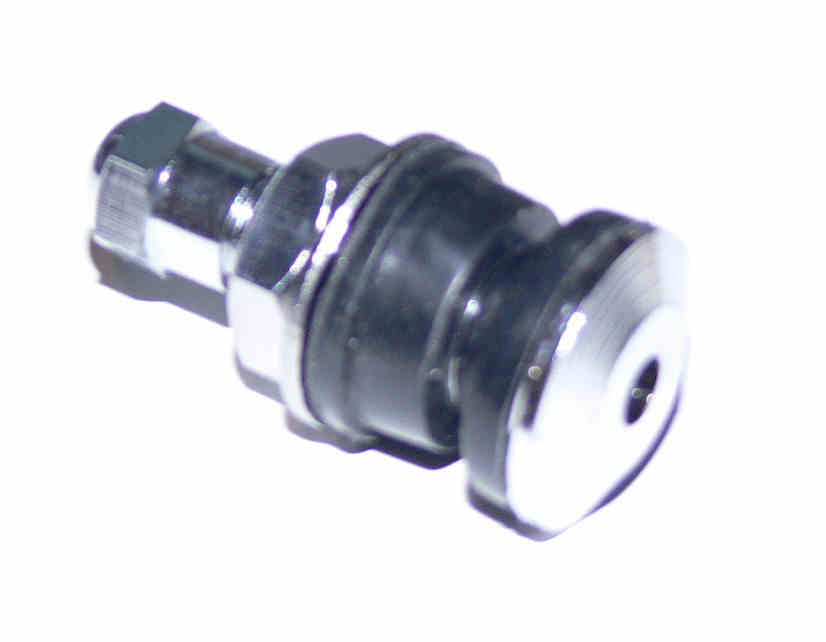
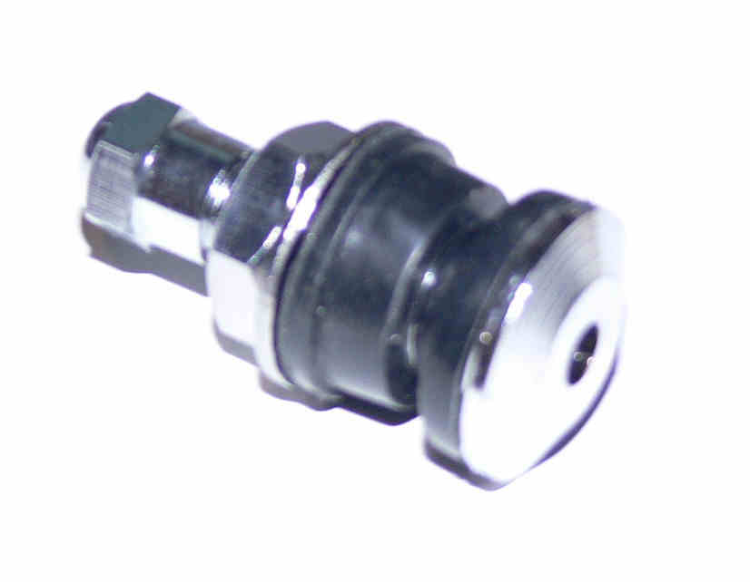
have quick release air hose
connectors for leak testing.
Pict . 007 The p-port final step cutter
I made installed in the end
mill. It is set at a 56.3 mm OD. Works like a
champ. Not shown is
the
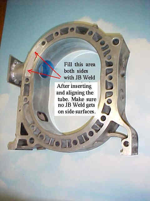
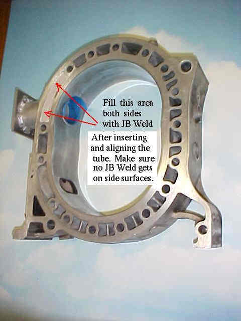
P-port insert 56 mm OD 50 mm ID which has
O-ring grooves cuts to seal
on the inner and outer sides of the water
chamber. It of course slips
into the port hole. No welding needed and is
removable, inspectable
and
changeable. Held there by the throttle Plate.
Throttle to be fastened
to the housing by four M5 studs that also hold on
the intake manifold.
Pict, 080. My design of a low profile low
restriction throttle.
Why?
In my application slide throttles are cumbersome and
won't get me up
close and personal to the p-port as I would prefer.
Hence the throttle
opening is over sized to compensate for
the 1.5mm SUS 304
thickness of
the throttle plate. It is 53 mm ID. The
throttle plates (two needed
and two to screw up trying) are laser cut ellispes,
slotted and to be
TIG spot welded in situ to the slotted 6 mm
Stainless 303 shafts.
Center
hole is for jig positioning. 303 on shaft
is much easier to machine a
1.5mm slot into while the material still has
good corrosion
resistance.
Shafts shown are not profiled yet
for minimal air resistance in
WOT.
Ditto the throttle plates but they will
be. One shaft will not
protrude from the throttle plate. The other to
the central housing
spring and cam location. Good advise courtesy
of Kinsler. Now looking
into baked on teflon paint coatings to see if they
have any measurable
merit in lowering air resistance in the intake
manifold parts. It
does
on prop blades.
Bearings are NTN BEAREE a tough fluorcarbon plastic
which is harder
but
more slippery than Teflon. I believe this is the
same material used in
motorcycle throttles. This material has been
tested on our wind
generator swing tail rudders for three years in the
field. These
tests
are equal to several million swing cycles with
no failures, at least
not in the bearing. Earlier tails had to be
strengthened as they got
beat up in the winds. Google "Airdolpin wind
turbine" to see it in
action. Now on sale in USA.
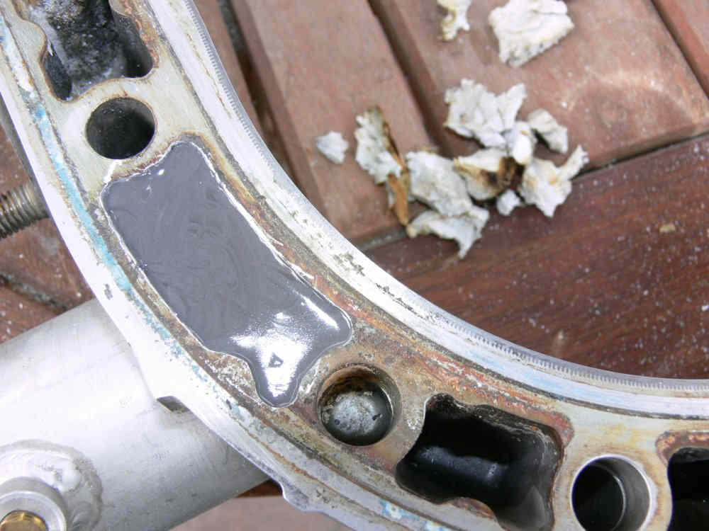
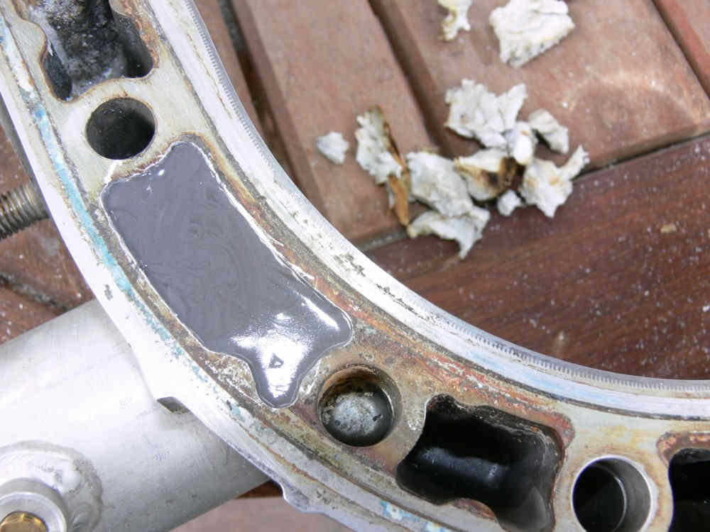
Other updates as they happen. The next
challenge is to cast a near
perfect finished epoxy face on to a new housing and
have it free of
inclusions. That requires a liquid AL. DEVECON
and application of a
vibrator.
Doug in Japan
How about applying vacuum?
Chris Cosman
Hi Chris,
Good idea in theory but the forms would need to be a
tight fit on the
various curved surfaces. The force of gravity is
adequate and the end
of the pour will be on the top edge of the casting which is
easy to
level with a hand dremel tool.
One trick is to pour the liquid down a rod inserted
into the cavity.
Then a use a large industrial vibrator or the type
they sell for
shoulder stiffness for a few seconds and any bubble will
just pop to the
surface.
Doug in Japan
Also consider pulling a vacuum on this assembly. I have done this
with with silicon potting compound on a small pneumatic manifold.
The end result is a bubble free, high gloss finish.
Erik Wahlstrom
Been there done that. We had so much trouble getting the
epoxy to seal all the crevices I looked for a better way.
The welded p-port and removable sealing plate was the break
through solution.
Paul Lamar
--
The Rotary Engine NewsLetter. Powered by Linux.
ACRE NL web site.
http://www.rotaryeng.net
Youtube key word UTUBPLEASE
Copyright 1998-2009 All world wide rights reserved.