I have questions about the installation of the seal blocks. Am I correct in
the impression that the holes for the screws should not completely
penetrate
the outer housing wall?
Is there a measurement of where to start the cut away for the blocks?
thanks
C. Smith
It is impractical for them to NOT penetrate.
Be careful when torquing them down as you could strip the threads.
Then you would have to install a heli coil.
Also if you pot the cavity with Devcon liquid aluminum or JB Weld first
the
blocks would be more secure. It is easy to bore through the Devcon.
Paul Lamar
-
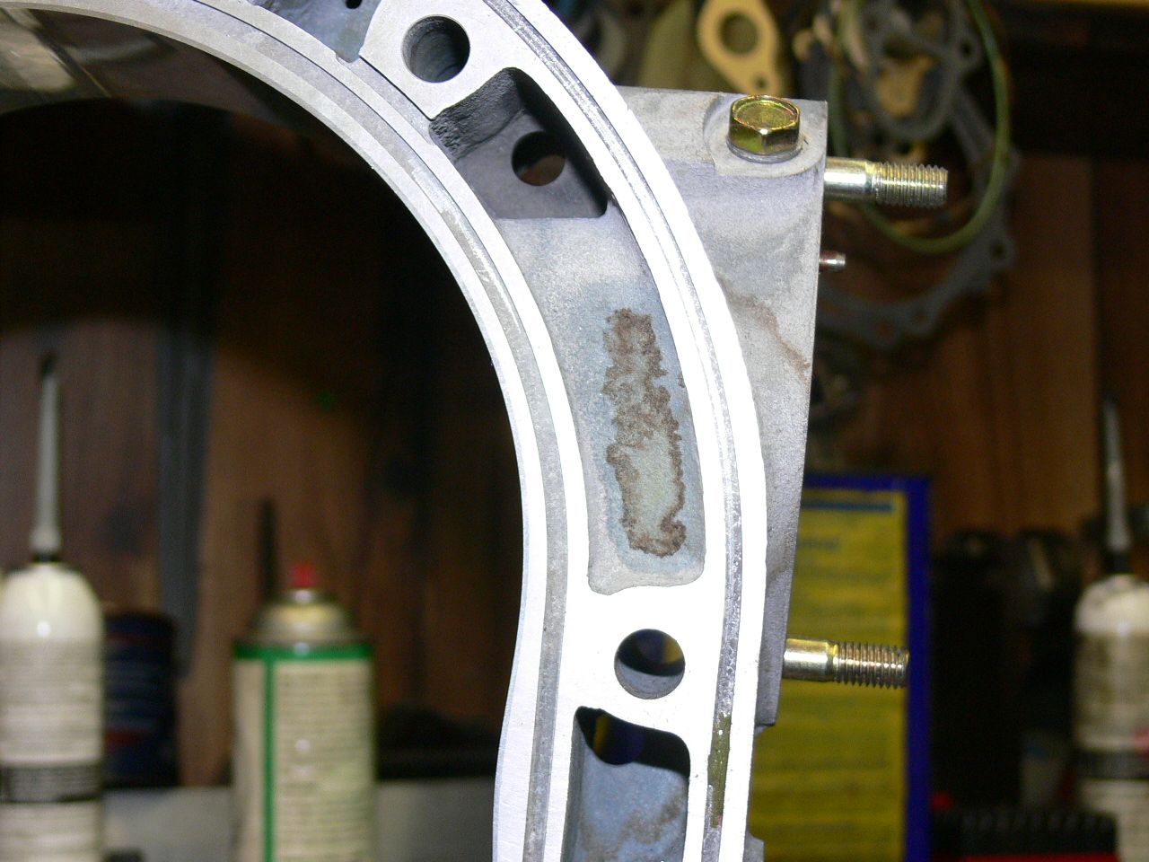
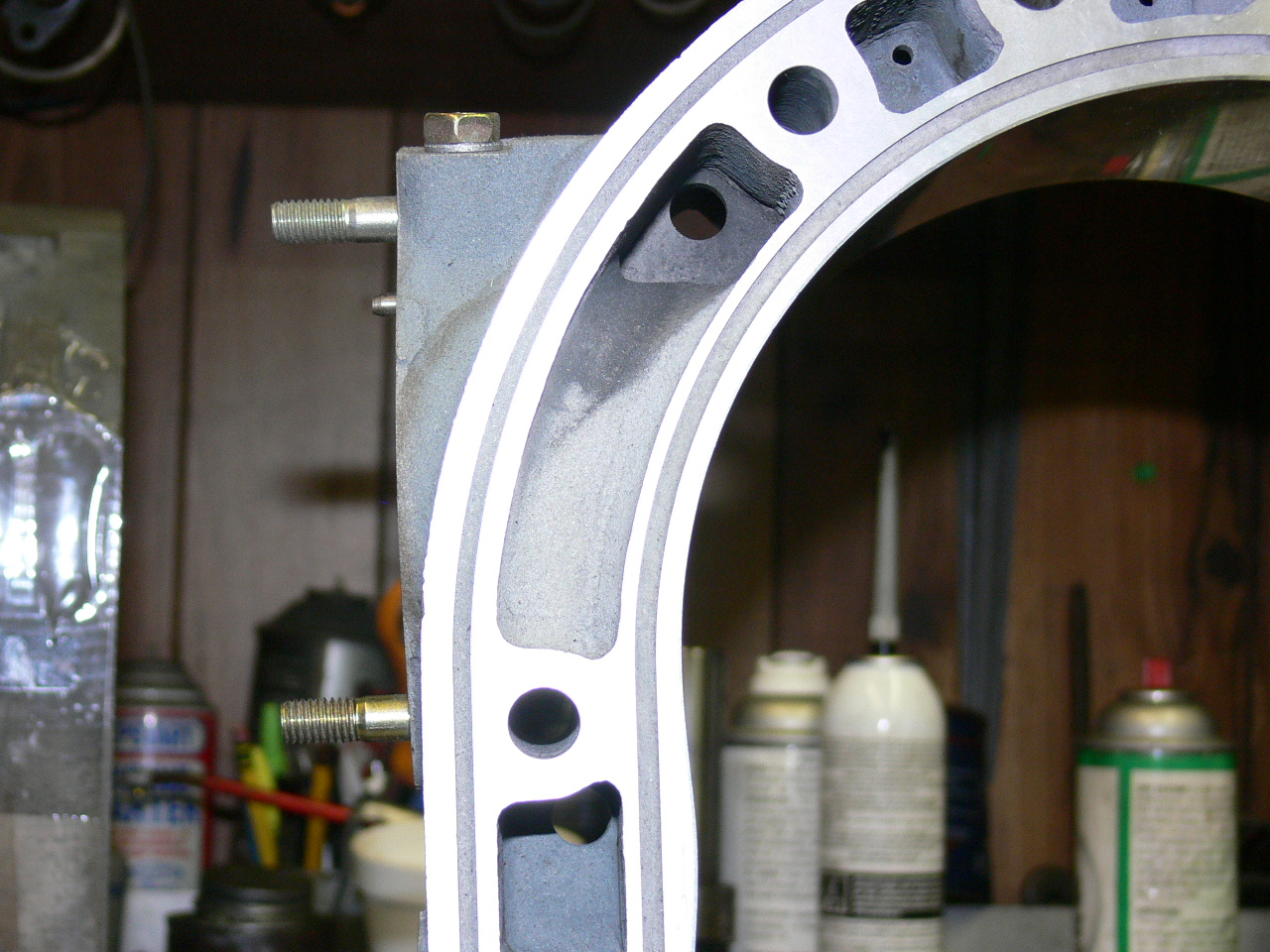
True, you bore through the OUTER portion of the housing wall so that there
is a "well" to cut threads into, but I think C.Smith's concern may have
been
over how DEEPLY does one cut THROUGH the thickness of the sidewall WITHOUT
drilling INTO the rotor chamber.
Paul Vermillion
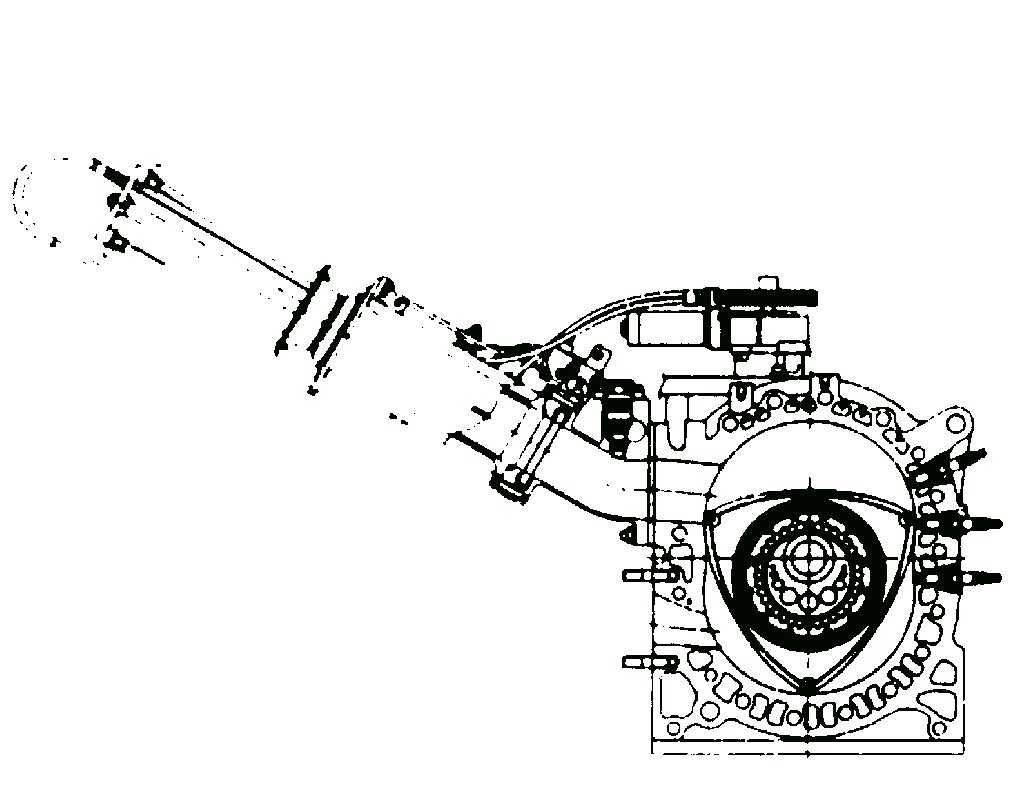
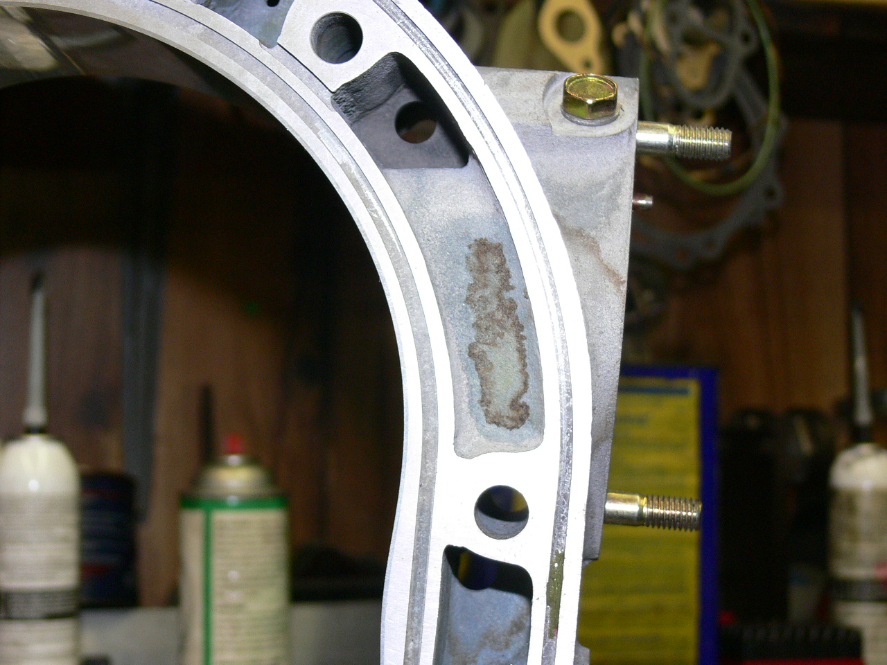
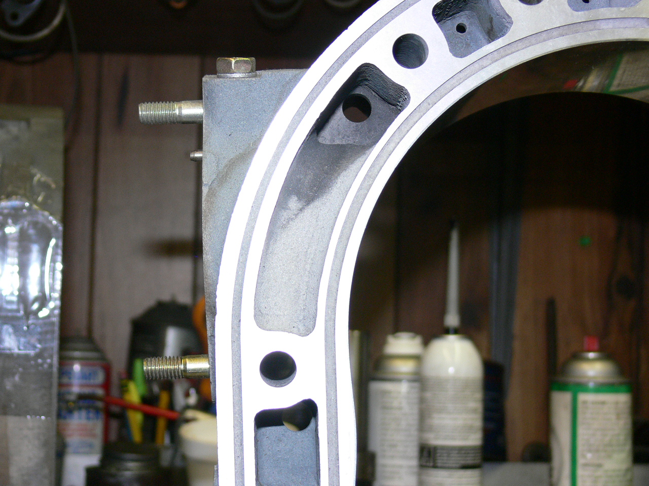
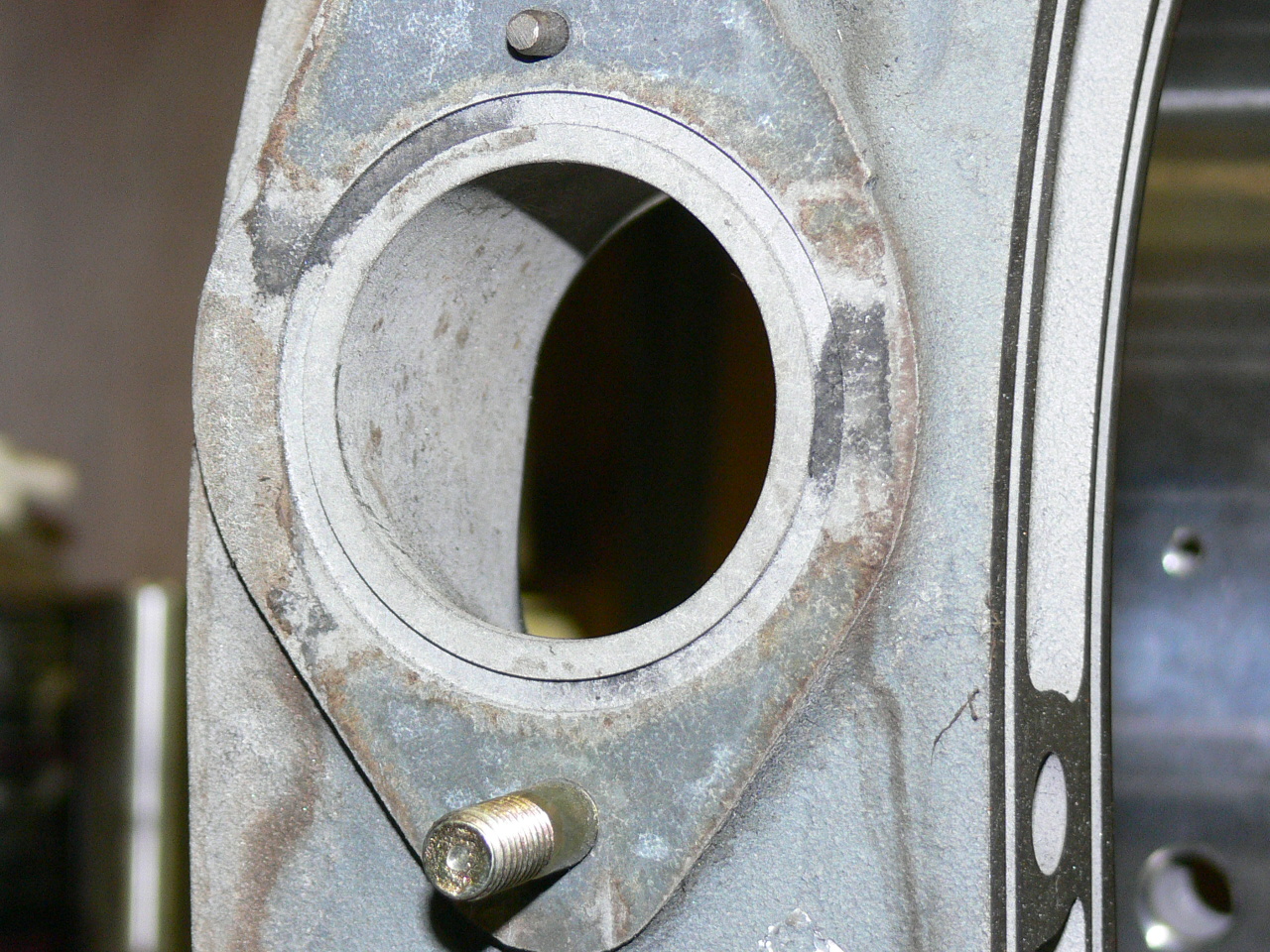
Not exactly. Here is the situation.
Paul Lamar
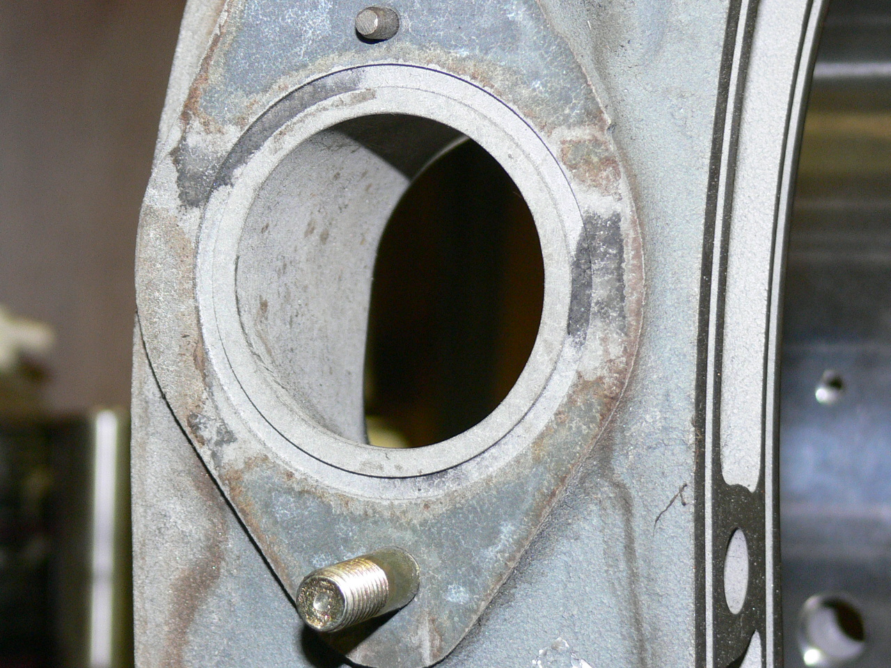
I realized that penetration was unavoidable, right after I went out to look
at the housings up close. Thanks for the clear images. Answers more
questions. I guess that since this is on the intake side, the
potted/blocked
water passages have little effect on cooling?
C. Smith
Correct.
Paul Lamar
Paul, IMHO everything between the water seal o-rings is in the wet area
including the clearance on the tension bolts and unused tension bolt
location.The devcon/jb weld filling around the stainless tube even on a
totally welded installation looks bulletproof. The concerns on cooling flow
have been tested by flight hours and 24 hour races at high power settings
which have more btu to dissipate than the car installation. From my research
it seems that this large open area of coolant flow at the P-port location is
intended to provide some heat to the intake charge for idle chararistics and
to reduce temp variation from the combustion side to charge cooled sides of
the engine to moderate thermal expansion of the parts. The areas from
approximately 7 to 12 oclock are the return flow through the engine. Many of
the slots have relatively small through holes so blocking this open area
must have some effect on flow as a percentage of total flow. I was wondering
if people building these engines drill any of the other through holes out
larger and if so which ones and by how much.
george grimes
That is an interesting area for discussion. I suspect Mazda put those small
holes in there to promote turbulence which improves the heat transfer from
the metal to the coolant. It appears the water jackets are over size.
The 16B on the other hand has smaller water jackets all the way around.
It remains to be seen how it cools under high power racing conditions.
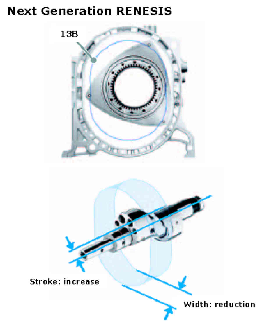
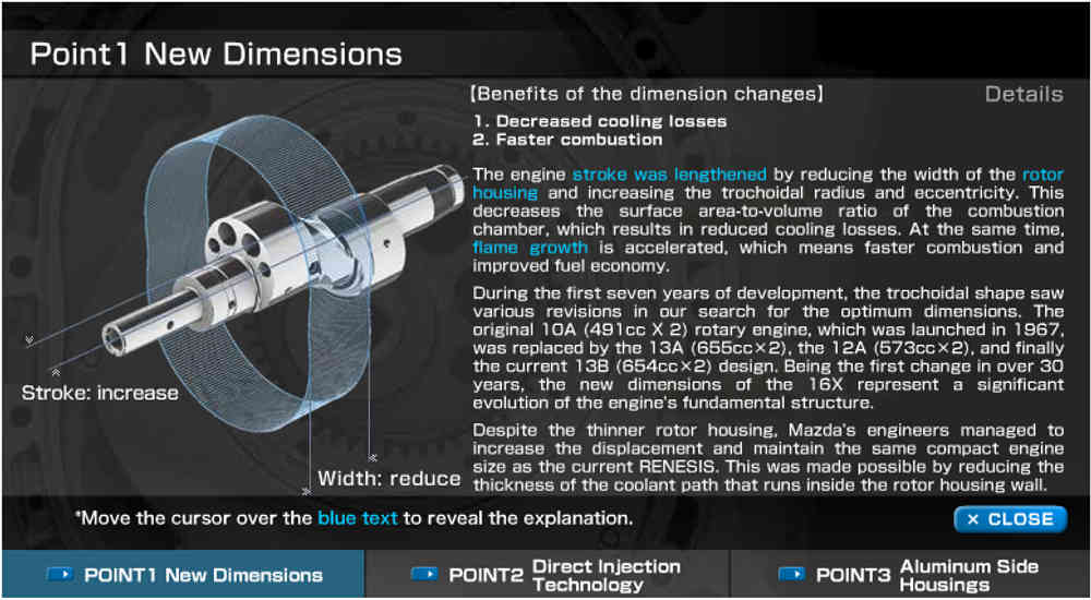
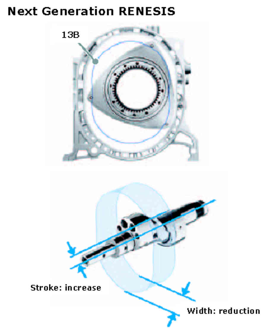
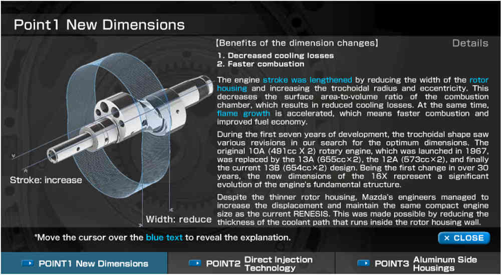
BTW the bit about surface area to volume ratio is wrong. It is the reverse.
A flat square box has a lower surface area to volume ratio than a long
rectangular box.
Lets say the box is 3 inches wide 10 inches long and one inch thick.
Surface area is 60 + 10 + 10 + 3 + 3 = 86 square inches.
Volume is 30 cubic inches.
S/V = 86/30 = 2.86
If the rotor was 10 inches wide the surface area 200 + 10 + 10 + 3 + 3 =
226 square inches. Volume would be 100 cubic inches.
S/V = 2.26
A cylinder with a 3 inch bore (7.06 square inches.) and a 3 inch stroke
would be 21.2 cubic inches. (7 X 3)
The surface area is 14 (top and bottom) + 9.42 X 3 = 42.26 square inches.
S/V = 42.26/21.2 = 1.99
The AIXRO and the Norton based engines have wider rotors with a more
favorable surface area to volume ratio IMHO.
My contention is the eff. of the rotary has less to do with the surface
area to volume ratio than is commonly thought. I think it is mainly
a ignition problem with a moving combustion chamber. So far to my knowledge
nobody has investigated the possibility of multiple firing of the spark plugs
many degrees apart as the mixture travels below the spark plug.
Paul Lamar
--
The Rotary Engine NewsLetter. Powered by Linux.
ACRE NL web site.
http://www.rotaryeng.net
Youtube key word UTUBPLEASE
Copyright 1998-2009 All world wide rights reserved.