Paul
How did Al Gietzen measure the water pump flow? in situ? If so I would
dearly love to know the flow meter he used as I would like to repeat
these tests.
Doug in Japan
The flow measurements were done on the dyno. The facility had large diameter
cooling plumbing, and a large radiator, so I expect the external pressure
drop was not very high.
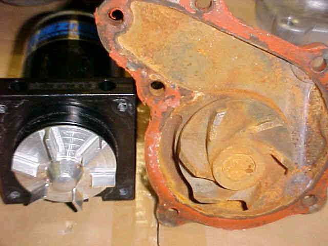
I don't know the details of the pump (year, model, etc.) as it came with
the engine from Dave Atkins, and the engine has a 12A front cover. Quite
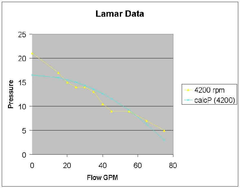
sure that it is not the stock 20B pump. The chart of flow data can be seen
at
http://members.cox.net/alg3/Dynamometer%20test%20report.htm
Scroll down to 'Flow Measurements'. Data is given for runs with and without
the engine thermostat.
Al
Al,
Thanks. Say do you know if the flow sensors Dave Atkins used were
electronic, mechanical, or a combination such as miniature turbine
wheel?
Doug in Japan
Dave Atkins did not do the test. It was done by a Southern California
aerospace engineer. If I told you his name I would have to kill you :)
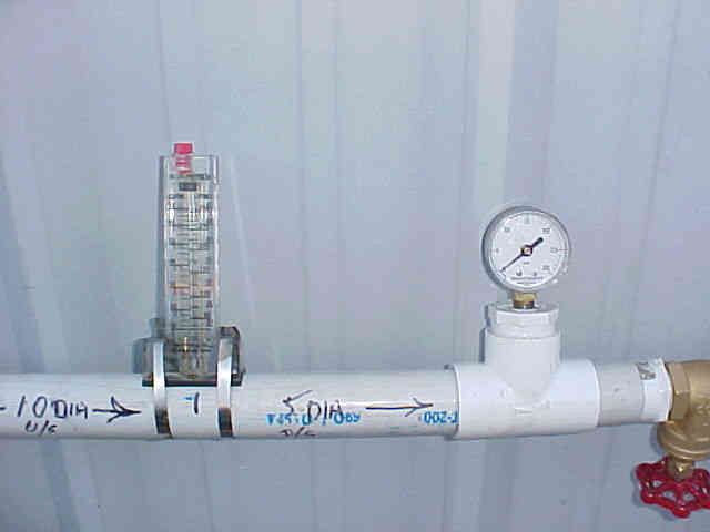
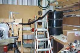
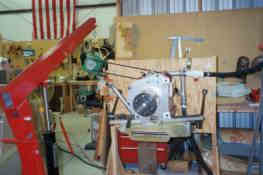
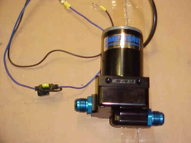
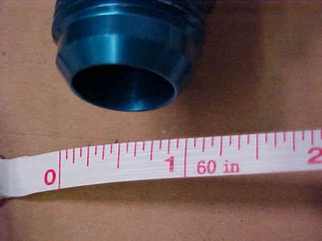
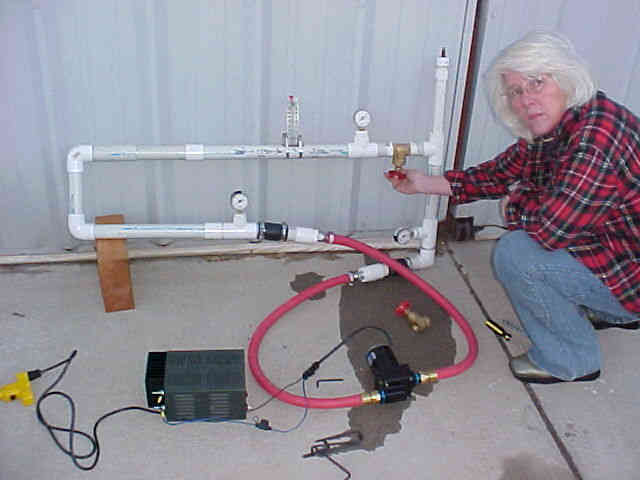
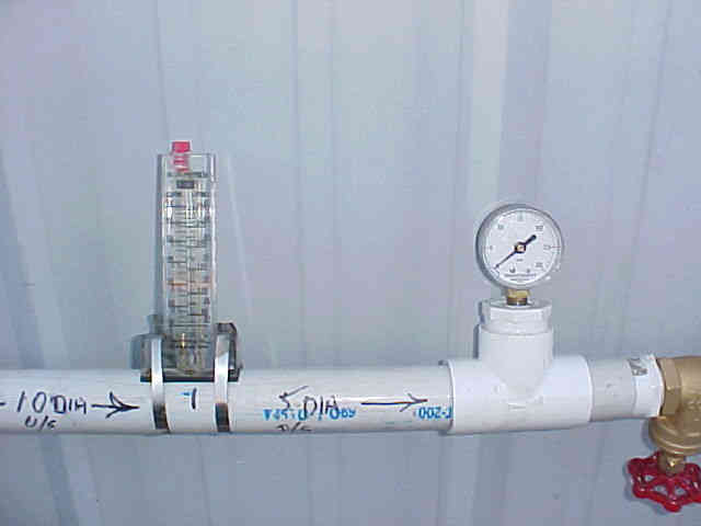
Here is the flow sensor I used.
Paul Lamar
Paul,
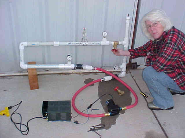
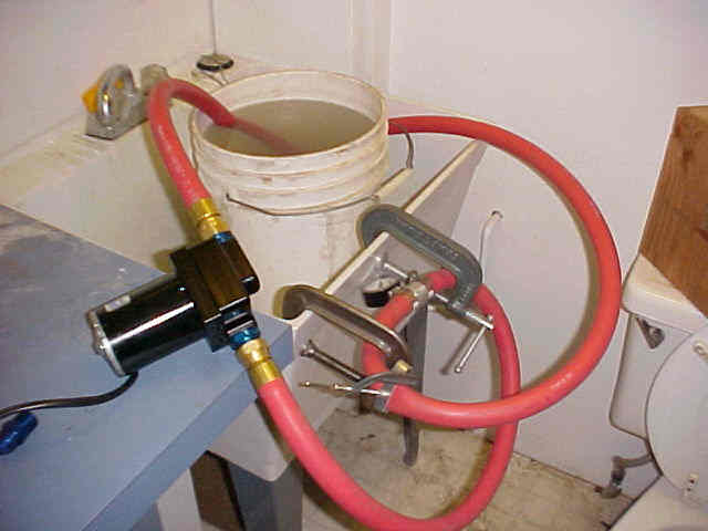
I know the type of flow sensor you used and the PVC pipe work. That is
what is suspect:) The Blue Line flow meters work OK (plus minus 3%) if
you have at least two feet of straight pipe on each side of them and
the flow is laminar. They aren't that accurate when there are bends or
induced turbulence nearby. A gate valve creates turbulence. I based
these statements on direct experience using identical units in at least
25 different industrial water purification systems.
All talk on water flow is academic unless the exact set-up as intended to
fly is tested. We know the Mazda pump works adequately IF. The 'ifs'
however contain many variables. Said another way, everyone's water
flow will be different depending upon installation details. Testing can
be done after the engine is running and installed but trouble shooting
and redesign is more expensive in time and money.
One (1) wrongly size fitting or sharp bend can reduce the flow 5%. To
do a meaningful system test, an electric motor should be belt connected
to the water pump mounted on the engine. Coolant is heated up to
operating temp. and keep there. Water flow is measured in the coolant
loop after it goes through the pump, block, water hoses, pressure can
and exits the heat exchanger/s. Coolant viscosity and temps. will
effect the results.
Doug in Japan
I was happy with +/- 10% flow.
The exact flow was of little interest to me as we were
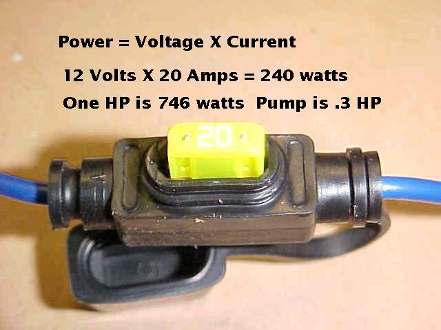
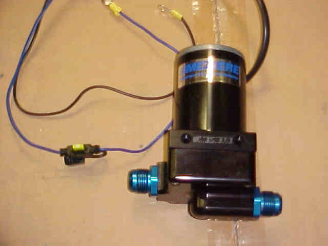
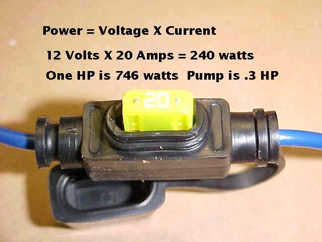
comparing them to electric water pumps with one tenth the HP.
Bill Schertz, Al Gietzen and I came up with more or less the
same results. Mazda also published similar data.
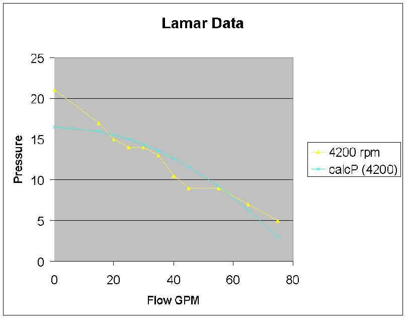
I was mainly interested in the HP required and flow verses
pressure. NOT the flow in an actual system. That is why
I used a valve to vary the pressure. It was a test of
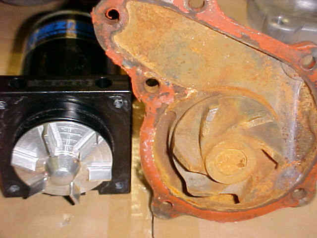
the impeller for the most part. The right angles just added
slightly to the pressure drop.
People were also using 1/2" ID cooling hoses. If you go from
1.25 inch ID to 1/2 inch ID the pipe area is reduced from 1.23
square inches down to .2 square inches or about 1/6th the pipe
area. That has a far larger affect than a 90 degree bend.
You do it and show us your data :) That is what science is all about.
Repeatable experiments. However you are not allowed
to criticize until you run your own experiments :)
Paul Lamar
--
The Rotary Engine NewsLetter. Powered by Linux.
ACRE NL web site.
http://www.rotaryeng.net
Youtube key word UTUBPLEASE
Copyright 1998-2009 All world wide rights reserved.