George,
Your comment about change in water flowcharteristics whenP-ports are
inserted in a large water passage isapertient observation. I
calculated that hole area is over 4.5 cm2.Waterflow in the coolant
system would have to reduce and/or thesystem backpressure increase to
maintain stock water flow when blocked. In affect it is like
shuttinga
downstreamvalve.I would think we wanthigher than stock flow through
the block as we are working the engine at higher power
densities.Anyone
with access to the Mazda Racing housingscould confirm thesize of the
holes in the water passages to see if there is a difference
betweenthem
and stock housings.
Doug inJapan
With the sealing block system water can still flow aroundtheSS p-port
tube. You don't have to pot the area with epoxy if you are
concernedwith
the
water flow in that area. If you do pot ityou may beable to drill
a 1/2 inch dia. or larger water passage.Another possibilityis a small
external return line from the rear rotor housing back to the input
tothe
rad.
This is commonpractice on Chev V8 racingengines.
I agree that robust waterflow is a good thing.
Theblockage is not that bad. You have tofigure the percentage of the
totalarea blocked and if you look notat the rotor housing but at the
centerhousing you will find thecenter housing side ports block a lot
of thereturn waterflow.
The bottom line is the metal temperature adjacent toboththe wear
surface
and the spark plugs explained in my book How to CoolYour Wankel.
Mark Steitle installed thermal couples in thatlocationand found
the temperatures a couple of hundred F below themetaltemperatures
in a Continentalliquid cooled aircraftpiston engine. Ihave tons of
data on this subject.
IMHO whatis far more importantis apex seal temperature which is
affected
byrotor cooling and apex sealoil supply. Hot apex seals wear faster
and
the apex seal slot itself wearsfaster. In fact the early RX8with what
turned out to be inadequate oilsupply to cool the apexseals resulted
in less than 100,000 mile life.Mazda addressed theproblem by adding
additional oil injectors about 2007.I still add a1/4 ounce of 2 cycle
oil to each gallon of gas in my 2004 RX8alongwith the regular
metering pump.
PaulLamar
I justchecked some factory race Periphery Port housings. At the top of
the
port cavity is a 25/64" [.39"] hole for coolant flow. Justone.
Lynn E. Hanover
Lynn
Very good. Thanks.Iasked because my O-ringed insert PP tube
effectively blocks the waterpassageway.There is however enough room
near the outer top of thepassageway to remove some metal and allow
water to flow through.Itake it the other cavities holes on the
return side are about the same asstock?
Doug in Japan
I will check on that in the AM and get back to you.
Lynn E. Hanover
Paul, I had a notion on testing my waterflow once I make some parts. I am
going to bolt the parallel flow center housing to a rotor housing
ondplumb
a garden hose to first the inlet and then the outlet and run the
waterinto
a 5 gallon bucket to time how long each side takes to fill the
bucketwith
flow through the rotor housing.I want to have slight back pressure
fromthe
return water to even out flow distribution on the inlet side water. I
came
up with a way to bypass/transfer the side housings so as not to restrict
flow through the rotor housings where seal coolingmight be improved.Look
on the rotor face side of the housings on the cast iron wear plate. The
solid models shoe a 1/8" thick blockage but that is removed with the
machining. Also all the part faces include a 3/16 inch machining
allowance
which is taken off with the lathework. all the holes are cncmilling
machined as are the ports.It seems lie a drilled hole through the
potting
mix is good insurance ifonly to purge air out of the cooling system or
trapped steam from the exhaust area below .
george grimes
Back in '02 I did actual measurements on the flow of the Mazda (13-B)
water
pump as a function of pressure and flow rate. I used a 55 gallon
reservoir,
and then timed how long to fill a 5 gallon bucket. Did it at several
different RPM, also measured the pressure drop across an evaporator core
as
a function of flow rate. The results are attached.I actually did a short
write-up on this, but cannot find the file. A couple of pertinent points:
1)
Max pressure of a centrifugal pump is generated at zero flow, 2) Max flow
at
zero pressure.The intersection of the resistance curve of the plumbing
circuit and the pump curve establishes where it is going to operate.
Bill Schertz
KIS Cruiser #4045
N343BS
Phase I testing
I probably have the write up Bill. I'll just have to search for it.
Can you offer any key words?
Paul Lamar
probably water pump performance or tests
Bill Schertz
KIS Cruiser #4045
N343BS
Phase I testing
Is this it?
------------------------------------------------------------------------------
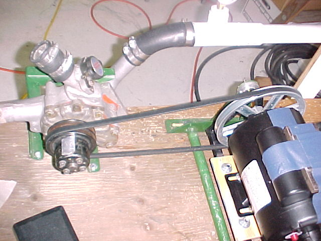
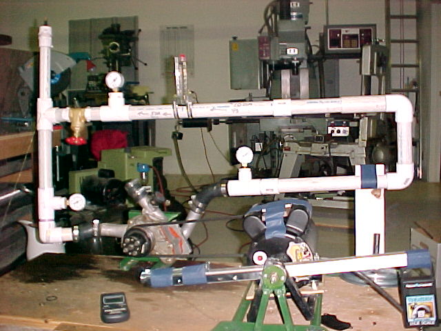
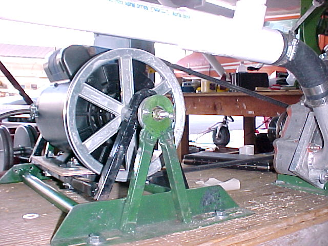
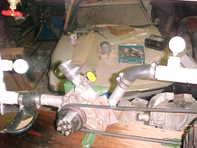
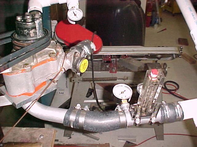
I reinstalled the 6" pulley and set up the flow system to pump
through my evaporator cores plumbed in parallel. Pictures are
attached. I borrowed a optical digital tach to measure the
actual pump rpm, however this created an unusual opportunity.
It works by counting pulses, and the flourescent lights give a
reading of 3600 rpm due to the 60 cycle current.
Therefore to
measure the rpm, I had to run it in total darkness with a
flashlight illuminating the pulley. I used two strips of foil
on the pulley to reflect light pulses back to the tach. The
pump rpm with a 6" pulley on the 3450 rpm motor was 5160 RPM.
I
then plumbed my evaporator cores in parallel as shown in
"Parallel cores" photo. These were hooked to the pump outlet,
and full flow tests were performed. Motor RPM = 3450 Pump RPM =
5160 Pressure generated at no flow = ~20 psi Pressure generated
at full flow, no evaporator cores in line = 2.5 psi Pressure
with cores in place = 8 psi Time to fill 5.8 gallons = 14-15
seconds (flowing through rads) = 23-25 gallons per minute.
Current on ammeter = 13 amps = 1560 watts 2.1 HP in ? Are you
sure you have that amp meter set right? Interestingly, the
current on the motor with no load (i.e. only spinning itself)
was ~10 amps, which I don't understand. Can someone who knows
more about motors help expain that?
Bill Schertz KIS Cruiser #4045
--------------------------------------------
Or was it the write up you gave at Sandy Bend.
I have that too but I will have to convert it to
a pdf.
Paul Lamar
Neither, the first was during the tests, and the [AC motor] current readings
don't make sense because the power needs to be read by a power meter, not an ammeter.
the [AC motor] current readings are meaningless.
The article I was looking for was a PDF file that had pictures and text in
it. I still have a hard copy and will scan it tomorrow night.
Bill Schertz
KIS Cruiser #4045
N343BS
Phase I testing
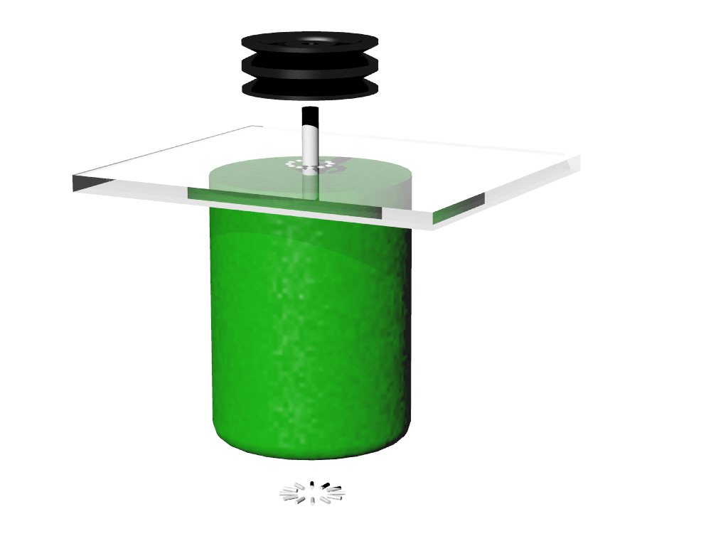
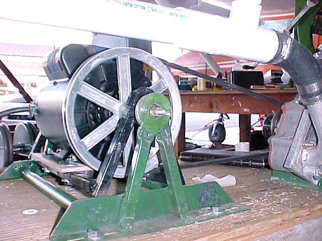
To be clear Vance and I measure the actual torque reaction on the 5
HP AC motor and used the RPM to calculated the HP consumed by the pump.
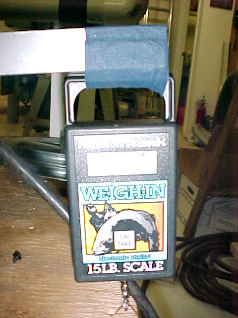
The AC motor was free to pivot around it axis and we used a
fish scale to measure the torque reaction on the AC motor axis. We did
not measure the current in the AC motor. Vance built the pump
dyno and I supplied the 5 HP AC motor. I still have the rig.
Doug is welcome to drop in, bring his own flow meter and use the
pump dyno to run the test again :)
Paul Lamar
--
The Rotary Engine NewsLetter. Powered by Linux.
ACRE NL web site.
http://www.rotaryeng.net
Youtube key word UTUBPLEASE
Copyright 1998-2009 All world wide rights reserved.