Hi Jarrett,
I am not doing this because I think this is a good way
to make a twin pusher. As my old late friend Vance RIP
used to say I am doing it because it is an interesting project.
In the mean times I am waiting for slide throttle parts.
The problem with spiral bevel gear sets is the separating forces
between the gears. This amounts to a point load of about
a thousand pounds at 200 foot pounds input. The traditional
way of handling this is use big heavy bearings and a heavy
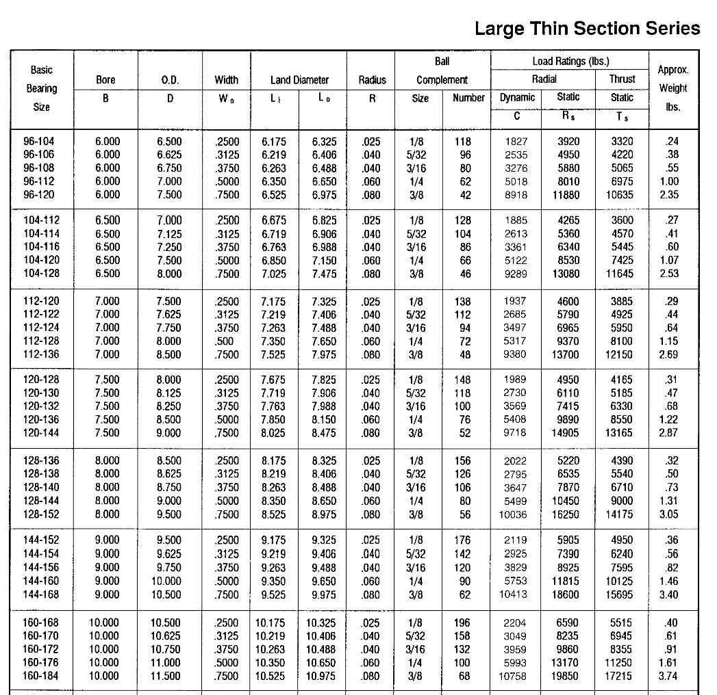
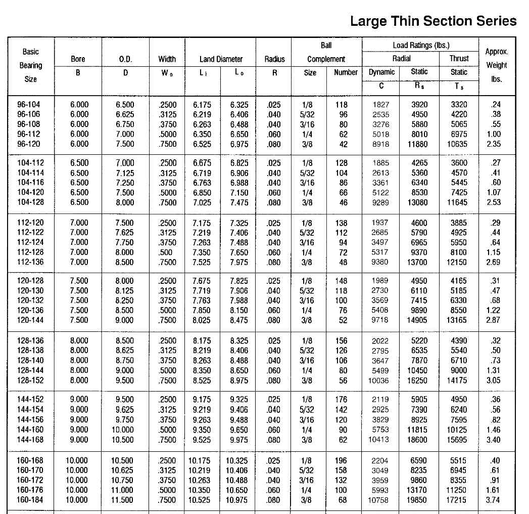
thick wall spool. I am thinking of using a large diameter, thin
section bearing to take the thrust load and a fabricated sheet metal
spool. The 3.5 inch carbon fiber prop shaft will be bonded
directly to the ID of the spool.
Consider the red device a rock solid buttress.
What does an FEA look like in the spool.
Material is 4130.
Thanks
Paul Lamar
Sorry Paul, just to clarify.. you want a 1000# linear force on
the rim of the grey part as well as a 200ft/lb torque load at the same point?
Any kind of finite geometry that I can use to put the load into [a hole or ...?]
I'll get the model in and ready for some loads :)
Jarrett
I don't need the torque load now. I am looking at some thin section
bearings and I want to get an idea how the stress will look
in the stationary ball race just behind the gear. I suspect the torque
load is inconsequential by comparison. The thin section bearing goes between
the grey part and the red part.
Paul
--
The Rotary Engine NewsLetter. Powered by Linux.
ACRE NL web site.
http://www.rotaryeng.net
Youtube key word UTUBPLEASE
Copyright 1998-2009 All world wide rights reserved.