Hi Jarrett,
I am not doing this because I think this is a good way
to make a twin pusher. As my old late friend Vance RIP
used to say I am doing it because it is an interesting project.
In the mean times I am waiting for slide throttle parts.
The problem with spiral bevel gear sets is the separating forces
between the gears. This amounts to a point load of about
a thousand pounds at 200 foot pounds input. The traditional
way of handling this is use big heavy bearings and a heavy
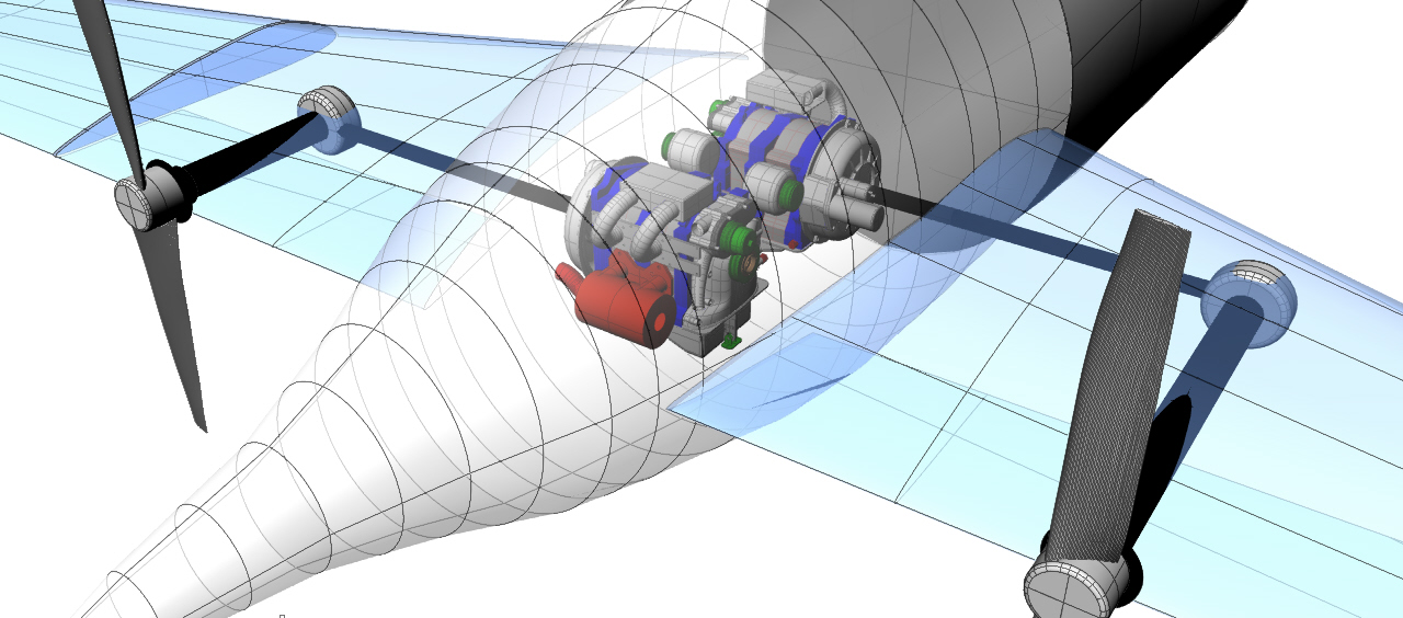
thick wall spool. I am thinking of using a large diameter, thin
section bearing to take the thrust load and a fabricated sheet metal
spool. The 3.5 inch carbon fiber prop shaft will be bonded
directly to the ID of the spool.
Consider the red device a rock solid buttress.
What does an FEA look like in the spool.
Material is 4130.
Thanks
Paul Lamar
Paul, As I remember the detroit car companies mostly use hypoid gear sets.
Do they also have large separating forces. I remember something from an
applied mechanics course when I was at the University of Pittsburgh in the
late 1960's. The lecturer said that gears were designed with one of two
curves. cycloidal was like the trace of a fixed point on the side of a
rolling cylinder, and involute was like the end trace of a string unwinding
off a cylinder. It was suggested that these two curves would make a rolling
contact point at the right center distance spacing with no change in
distance to either of the shaft centers. Having the wrong center distance
would cause the driven gear to increase and decrease speed at every tooth
contact due to the small change in the contact point to shaft center
distance.
I used white grease to get the contact point right and flank space
for lash on the carrier bearings. There was considerable practice with a
chrysler hemi in a sprint car. In looking at the conceptual design above,
how about a pair of timken bearings on the small end of the spool for radial
and thrust loads and a large diameter spherical roller on the larger end for
the radial loads there. This would reduce the required size of the thrust
bearings which seem more rpm limited in the larger diameter.Will a universal
joint be necesary on the ford pinion carrier cartridge for access to the
shaft nut that retains the pinion bearings or could it be a flanged plate
with half round drive pins on bach that bolts to the yoke where the
universal joint caps would bolt up.
The flange might run smoother and allow
the drive shaft to be bonded to a flanged steel tube. One unrelated thought
is that if the engines can not be located far enough behind the firewall for
CG while keeping the drive shafts inside the wing, the use of a full
length gearbox to gearbox drive shaft tube with hyvo chain reduction off
each engine would keep both props turning with a shut down engine. Also both
engines could be right side up and pointing in the same direction. I think
the original sketch Jean posted showed one engine turned 90 degrees for
exhaust manifold construction prposes. A full length shaft eliminates
asymetrical thrust issues and prop synchronization. I am a real fan of Tracy
Crook's PSRU but if an offset s needed to gear the drive shafts up to a
thicker section of the wing/and or CG isues are a deal buster this could be
a way out.
george grimes
The beauty of this design is the right angle drives do double
duty as prop speed reduction units. There are no U joints in the
prop shafts. Just the lateral shafts from engine to gear box have u-joints.
Those I suspect can have stock carbon fiber RX8 drive shafts.
Hyvo chain boxes are heavy. I used one in a mid engine Firebird
I built for Pontiac way back in 1968 :)
No problems keeping the lateral shafts inside the wing.
Paul Lamar
--
The Rotary Engine NewsLetter. Powered by Linux.
ACRE NL web site.
http://www.rotaryeng.net
Youtube key word UTUBPLEASE
Copyright 1998-2009 All world wide rights reserved.