Good morning Paul
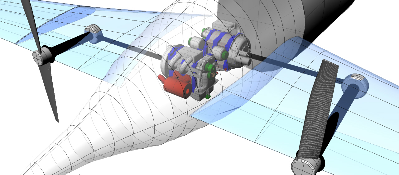
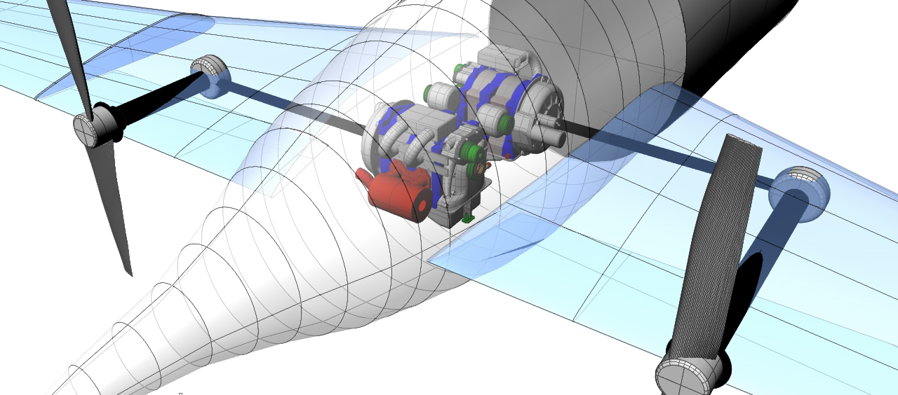
I am sending you a sketch the way i am looking the
reduction angle drive with all components ,check it and come back on
your own view
Jean Prudhomme
Nice sketch Jean.
I took the liberty of modifying it the way I think it should be done.
IMHO using u-joints on the prop shaft adds unnecessary weight and
torsional flexibility.
It is up to you of course.
Paul Lamar
Jean Prudhomme wrote:
Paul what are you doing for the reverse trust when engine is lost and
prop dragging on the air stream crating a reverse trust on propshaft??
How are you attaching the prop flange to the main carbon fiber tubing??
Jean Prudhomme
The carbon fiber prop flange would be bonded to the carbon prop shaft.
About the only practical thing to do is find an electrically adjustable prop that
will feather. I don't think you are going to come up with a workable hydraulic
constant speed featherable prop system with this arrangement of angle drives
and carbon fiber shafts.
If you make everything out of steel to tolerate the oil 200F temperature it will be a
huge weight penalty. As a I said before put two engines on the wings and talk
Mistral into selling you a couple of constant speed gear boxes and forget it :)
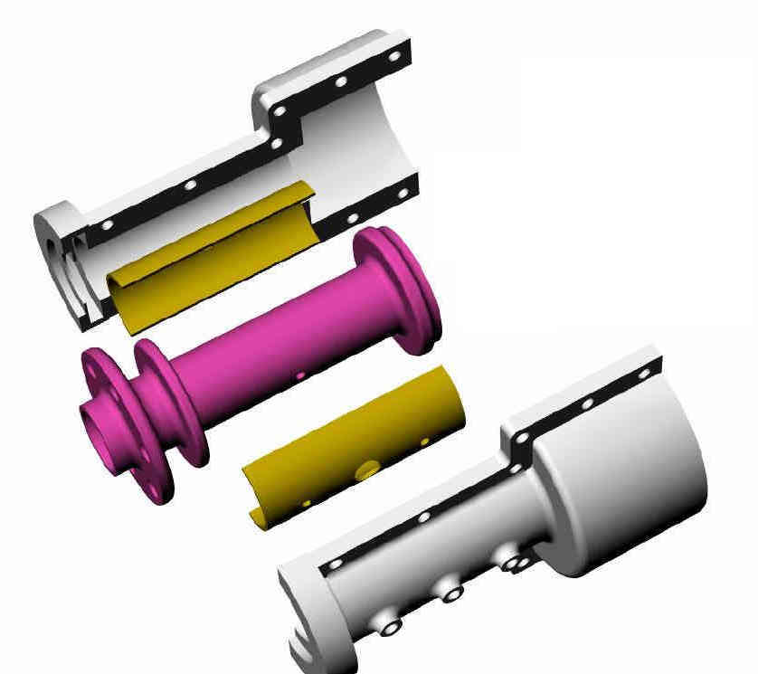
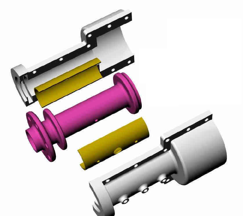
Perhaps Jeff Doddridge can build us a planetary constant speed prop gear box
like these 3D's.
Paul Lamar
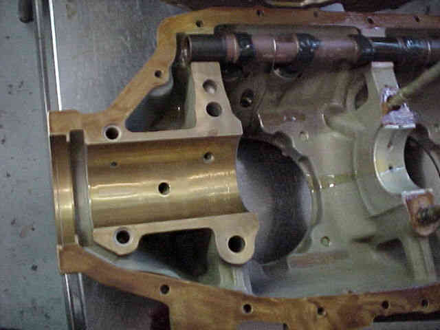
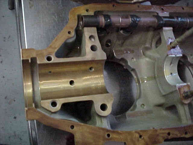
On the picture below as lyc, main bearing-cs-with housing
Do you have some dimentions on this design i like it the way it is and we
can had a spline shaft at the end to go on the std spool,
Jean Prudhomme
It is based on a stock Lycoming front main bearing whatever size that is.
I don't have one to measure it. It is a copy of the front end
of a Lycoming engine.
It is designed to be attached to a stock Mazda high pressure die cast
light weight bell housing and used as a planetary gear constant
speed prop PSRU just like a GITSO.
I don't recommend it for your application because it will be way
too heavy and way too torsionally flexible when you add flanges,
splines, U-joints, tapered roller bearings, stock spools and shafts.
You would also need to beef up the aft part of the nacelle to take the
650 foot pounds of local bending loads due to gyroscopic reactions
from the heavy constant speed props when the aircraft is stalled or
rapidly yawed due to turbulence. This will add a lot of airframe weight.
A long one piece large diameter carbon fiber prop shaft drastically reduces
the local bending loads on the structure due to prop gyroscopic reactions.
Only much smaller lateral and vertical loads would occur near the prop bearing.
The helicopter bearing in the custom angle gear box with the custom spool
takes out the much lower loads due to this gyro bending reaction.
IMHO the only way to make your layout practical is cut the number of parts
and use a long one piece carbon fiber prop shaft incorporating the custom angle
reduction drive and spool on one end and the prop flange on the other. But that
is just me and the way I would do it.
Paul Lamar
The Rotary Engine NewsLetter. Powered by Linux.
ACRE NL web site.
http://www.rotaryeng.net
Youtube key word UTUBPLEASE
Copyright 1998-2009 All world wide rights reserved.