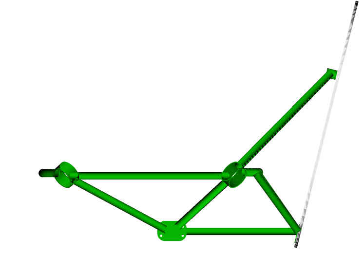
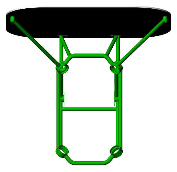
Here is the latest with the new dimensions. Still needs some minor
tweeks here and there.
Paul Lamar
Paul what is the plan to split the cowl [vertically or
horizontally? Connection type?
Are we just making a foam buck over which Mark is going to lay up
glass and then
hack out the foam?
Jarrett
I think it is best to split it horizontally for service reasons.
The foam buck however could be split vertically as then you would
have a mirror image. I can do the 3D either way.
ops I forgot to answer the connection type.
The bent piano hinge trick is popular.
The top is held together with a piano hinge.
You remove the wire to separate them.
Paul Lamar
Alrighty, we can split it either way.. I imagine it would be
shorter if
we split it vertically thru the
spinner? I'm still a little limted in 'Z' depth so the shorter
it is in this dim the best..
Interior ducting can easily be done either as a buck or a female
buck/mold. Either will take a little
to finish as they wouldn't be true 'mold's [as in waxable..] Mind
you I can do that as well..just
takes more time and some more exotic materials..
It's been a few years since I used Rhino.. does it have zebra
curves to check the surface smoothness,
and blends across joints [curvature continous curves across joint
lines]?
I'll have to send some pic's of parts I've made like this on
the mill... did a world record setting kayak
two years ago...
Jarrett
I think we can use insulation foam and cover it with saran wrap
and scotch tape.
The imperfections would be easy to sand off the buck.
The short way would be a horizontal split as the total cowl
is only 31 inches high while it is 46 inches wide.
No zebra curves as far as I know but people tell me it will load into
Solid Works.
You do the whole thing and then split it on a plain.
Paul Lamar
Sure Paul, I can give it a whirl... can I get you to send me what you've
got so far [model or dim's] and I'll play w/ it from there? Your correct,
Sw can open Rhino files directly if you want to go that route.
Jarrett
I need to do some more tweeking.
Paul Lamar
Paul,
The tunnel on the firewall has straight sides. The roof is streamlined to
encourage airflow through the tunnel. The cowl portion is basically a
half-circle, as shown in these pictures of an ES cowl (not mine). I feel
that my installation would benefit from slightly larger tunnels than these
in order to improve exit airflow.
Mark S.
What is the thinking on these? Theory?
It is not obvious to me.
Paul Lamar
That's how the heated air gets out of the cowl. It is also normally where
the exhaust exits. The attached picture shows the two tunnels and the
cowl
flap of my current design.
Mark
Nice picture Mark. Do you have a large radius on the lower edge of the
firewall just above the flap?
Paul Lamar
Paul,
No, I didn't at first, but I did add one later. Every little bit helps.
I'll see if I can get a picture of it for you. It is basically a thin
piece
of aluminum bent into the shape of an upside down question mark and
attached
to the lower firewall lip.
Next, I would like to add sides to the cowl flap.
Mark
That sounds OK.
I think I figured out the reason for those two tunnels.
It is an attempt at dual augmenters... AKA exhaust ejectors.
Since the AC engine has dual exhaust it makes sense to try
to do this. In our case there is just not enough room IMHO.
Paul Lamar
Paul,
I'm not so sure about that. Most of the Lancair guys run the exhaust pipes
out through the exit holes far enough so that the exhaust doesn't soil the
belly. I think the tunnels are there to help scavange the heated air out
of
the cowl at an angle close to the relative airflow across the lower fuse.
Mark S.
Well then they should :)
Check out an early Cessna 310 it has real augmenters. I have a picture
around here
someplace. Of course in the ES one would have to have SS tubes in there
to keep the composite from melting.
I like the side flaps idea. One on each side or just one on the right
behind the rad. Six inches wide by about 20 or 25 inches high.
Paul Lamar
Paul,
Side cowl flaps won't work because the end of the radiator will be up
against the firewall.
Mark
Are you sure? You have 51 inches from the top of the firewall to the
spinner while the rad is 28 inches long as I recall. Let me do a top
view rendering of what I have so far.
OK here it is. Lots of room!
In general you cannot move the side rads all the way back because of
the motor mount. I have a dwg someplace of your current MM so I have
to add that in.
I still need the thrust line position down from the top
of the firewall just as a reminder.
-------------------------------------------------------
Does this motor mount look about right?
What I don't have is the exact shape of the firewall
which we will need to make a buck. If you give me the coordinates
of one side and I can take it from there.
BTW how did Lancair resolve the MM cracking issue?
Paul Lamar
--
The Rotary Engine NewsLetter. Powered by Linux.
ACRE NL web site.
http://www.rotaryeng.net
Youtube key word UTUBPLEASE
Copyright 1998-2009 All world wide rights reserved.