This subject keeps coming up from time to time.
I thought we had it put to bed years ago :)
The p-port valve overlap is of no consequence in a high RPM, high power
aircraft
engine just like it was not a problem on the 1991 LeMans winning
engine and
the p-port 3 rotor engines now running and winning in the Rolex GT
races.
These Le Mans engines had the lowest BSFC every achieved in a rotary.
The stock side port RX8 engine has no overlap for Hc emissions
reasons at
idle and low rpm low power typical in automotive use.
Those engines in the Rolex GT RX8 are old 3 rotor engines with p-ports.
P-port engines have won many 24 hour races back in the 1980's.
There are no apex seal wear issues as the p-port area is a very
benign part
of the rotary. There is no pressure difference across the apex seals as
they
pass over the p-port. The 13B p-port hot exhaust is far far harder on
the
apex seals than a much cooler p-port intake.
The RX8 side exhaust/P-port intake is particularly good combination
as it idles as well as any 13B with side intake and p-port exhaust.
Read:
http://www.rotaryeng.net/fund-of-intake.html
http://www.rotaryeng.net/Welded-steel-p-port.html
BTW what is the valve overlap in a turbine engine?
The rotary comes far closer to a turbine engine in this regard
than any piston engine.
Paul
We drove the Pport 75 tube frame to the false grid. The Bridge ported 95
tube frame had to be towed with a tractor. The Pport was quite docile
even
with a 1:96 -1 first gear.
Lynn E. Hanover
Paul
Is there any specific distance from the exhaust port to the intake
P-port that has been identified other than just popping a hole in the
center of the round boss in the casting??
Is there a better optimum shape other than the round hole with the
identified size...with a position to match??
Isn't the P-port and turbo combination a match made in haven because of
the large overlap and relatively mild RPM(6000 to 7000) keeping exhaust
gases from finding there way into the intake stroke???
I know these are old questions that have been addressed probably long
ago, but I had to ask......
jeff
The proper dimension is the same as the Lemans engine.
8.64 up from the bottom.
Paul Lamar
Paul,
Is "8.64" a typo? The drawing shows 8.55". Can you confirm which is the
correct dimension to use as the center for boring the p-ports?
Thanks,
Mark
8.64 Mark. Send me the dwg with the typo so I can find it.
BTW I skinnied up the nose.
This rad IS 18 inch high and 30 inches long overall.
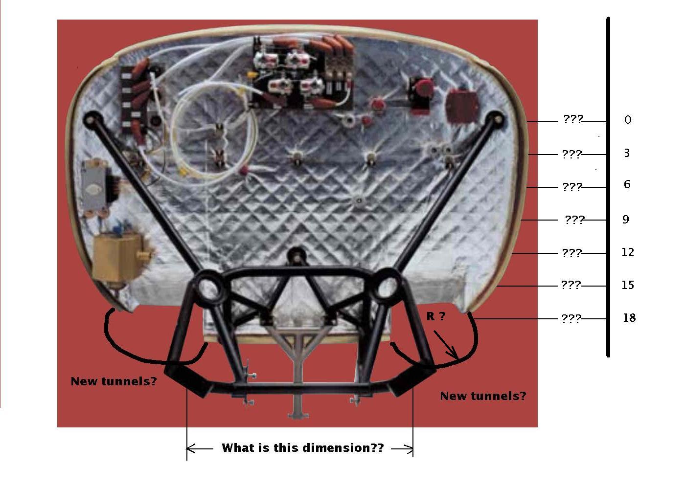
Here is all I have on the firewall shape so far.
The contoured SS tubes should be in any day (Larry?).
Paul Lamar
Paul,
It was the view of the Lemans engine with the p-port dimensions up from the
pan flange. The dimension to the port centerline reads 8.55".
Mark
Is this it? Your supposed to split the difference :)
It also reads 8.71 :)
8.55 + 8.71 / 2 = 8.63
.1 inch one way or another will not be noticed. It is not like each
tenth of an inch is worth 10 HP :)
Paul Lamar
Paul,
Yes, that's the drawing. I assumed that the most important measurement was
the one locating the port at the inner liner. Since most people bore the
hole straight in, I assumed the 8.71 dimension was irrelevant.
Mark
It is all scaled anyway so the 8.64 is somewhat arbitrary.
Speaking of scale I can use this as your new firewall shape if you wish.
The firewall shape is the key to the overall cowl shape.
To be really accurate... to make a new NC foam buck mold we would need the
coordinates of one side and the coordinates across half the top curve.
I will then mirror them using the width and height dimensions.
Use a 2x4 set back at 14 or 15 degrees (to match the firewall angle) as a reference
and take measurements ever 3 inch down starting at the upper motor mount
hard point. The fore and aft angle of the 2X4 should be aligned parallel
with the aircraft center line.
Paul Lamar
--
The Rotary Engine NewsLetter. Powered by Linux.
ACRE NL web site.
http://www.rotaryeng.net
Youtube key word UTUBPLEASE
Copyright 1998-2009 All world wide rights reserved.