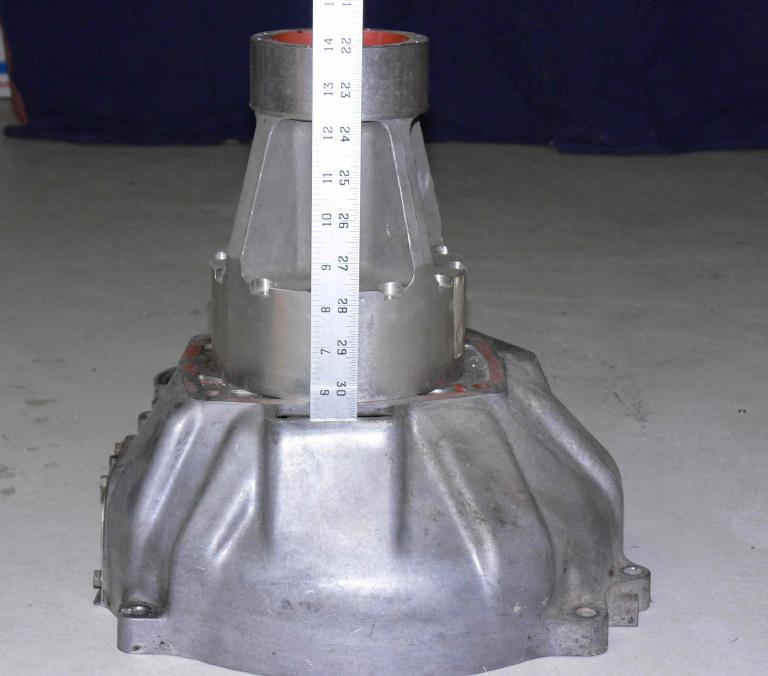
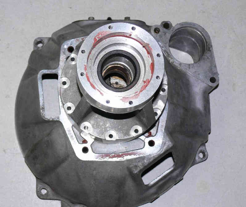
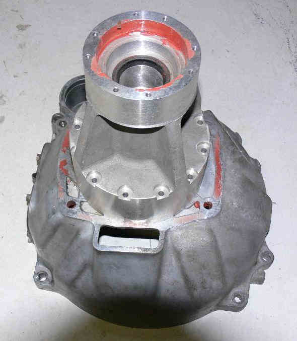
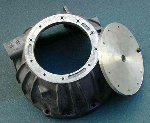
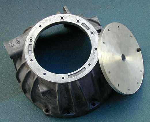
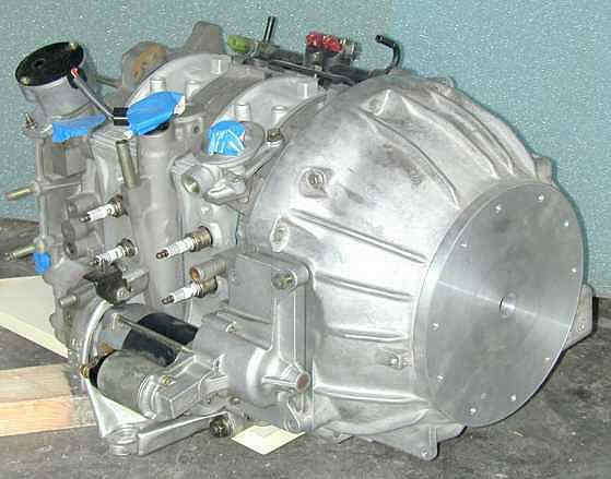
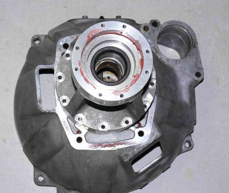
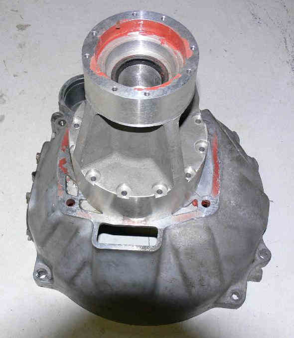
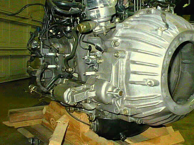
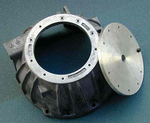
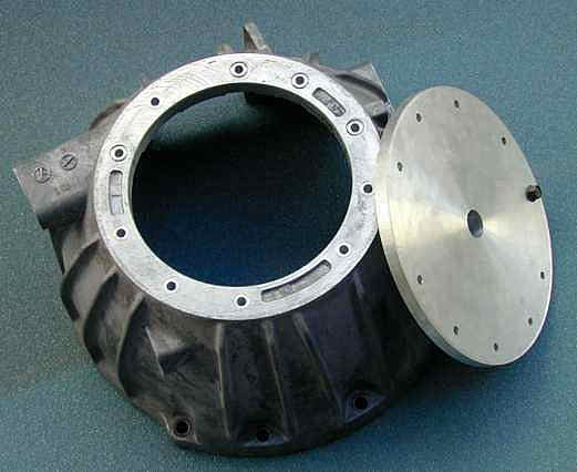
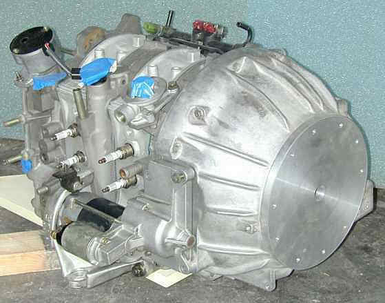
A few minor problems for the 13B. One hole was ten thou
off or so but it could be drilled out with no problems.
One cup tab was a bit too long so that could be hacksawed off.
We had a few typical bolt circle problems but easily fixed by
drilling the holes out to 27/64th instead of 10 MM.
Other than that the 13B was usable. The starter hole
was a bit on the small side but I can set it up in my
cheap Chinese mill and bore it out about .020.
The starter hole should be 2.640.
I was working from Tracy's dwg and I should have
checked the dwg against Tracy motor plate which I also have.
The drawings had a few errors and I probably made one or
two my self. The dwg does not match Tracy's plate :)
The RX8 extra bell house bolt was way off by about a half inch so
that is going to require a whole new dwg which I have about done.
I want to make the plates fit both the 13B and the RX8 motor.
Jeff I'll get the fixed dwg to you in a day or so.
Paul Lamar
Paul
So this is usable. If you want I can open up the starter hole here. It
measures 2.620 on the solid model. I depend on the solid model for
geometry for expediency. If you need to digitize the bolt pattern on the
housing we can do that. We need absolute numbers. I do not know the
difference between the RX7 and 8. the half inch hole problem, does that
make it unusable??? No worries, we just get it right for the folks that
need them...
jeff
I'll ship it back if you want it. I only have one RX8 end housing
and it is on my RX8 P-port test engine which I don't want to take apart.
I think I got it measured fairly accurately.
If you have a 13B end housing that would be a good one to digitize.
The solid model is now fine. I fixed it. Jarrett has it now and
he is converting it to a Solid Works file for you. I made a couple of
other changes while I was at it. After you do it three or four times
you get better and faster. The new version is much more accurate as
I had been there and done that :) All ribs are now the same width and
parallel. We need to drill all the 10 mm holes out to 27/64th as that
will ease the bolt circle problem.
No change in the back pattern.
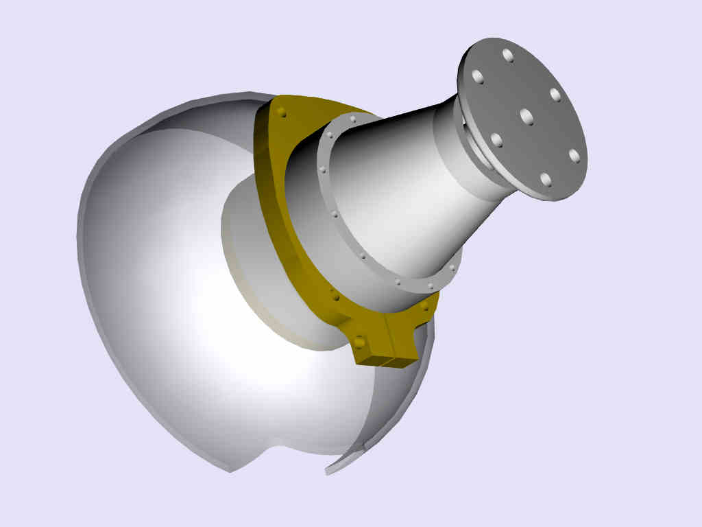
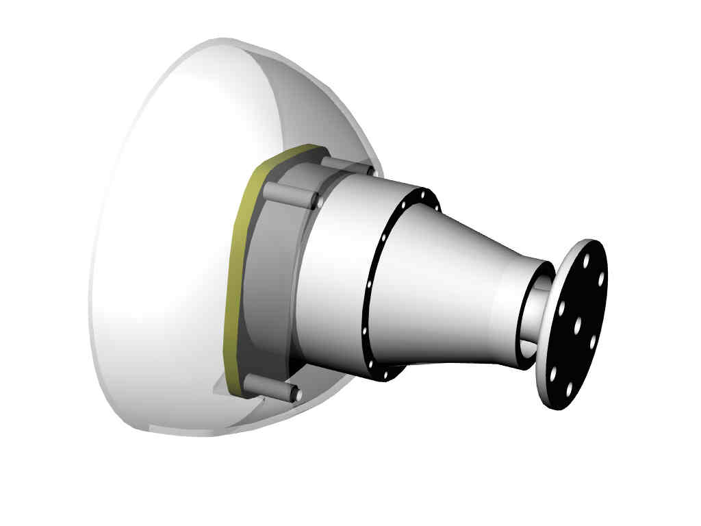
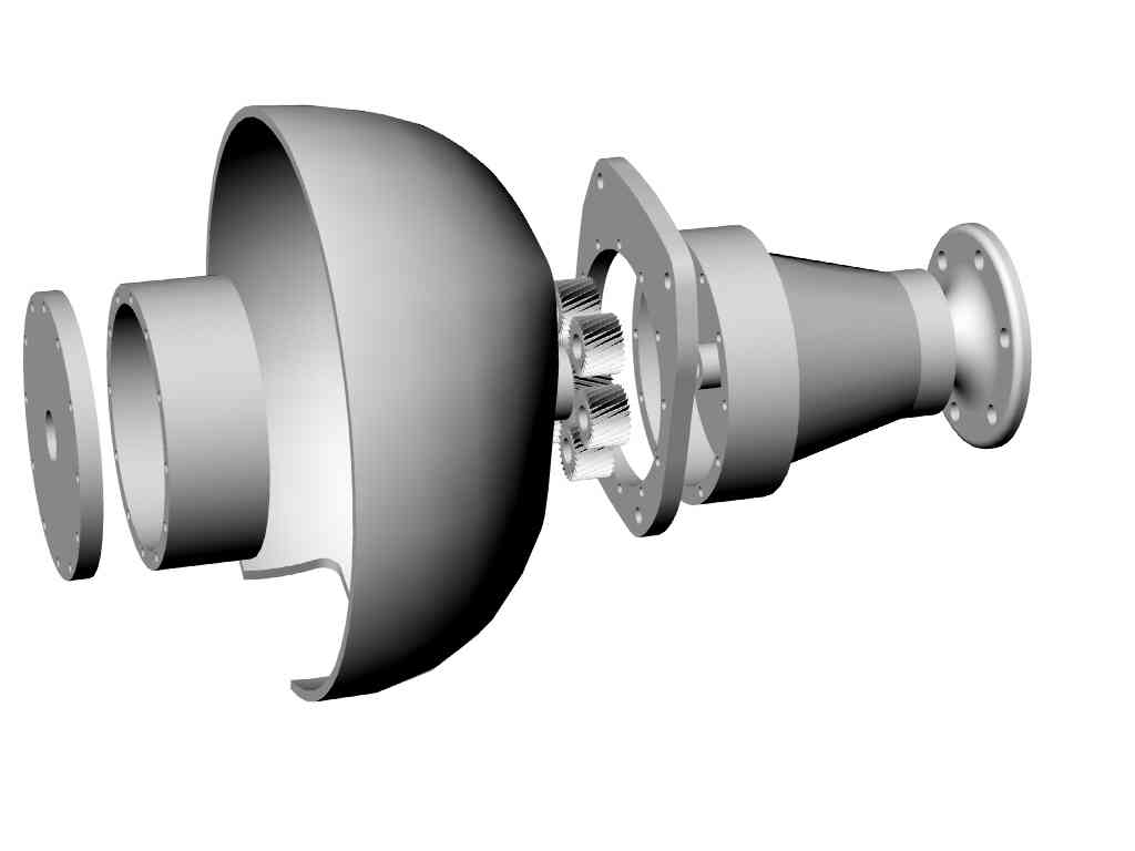
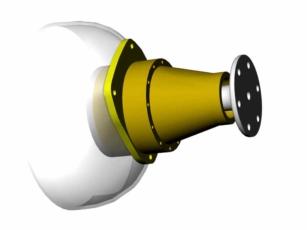
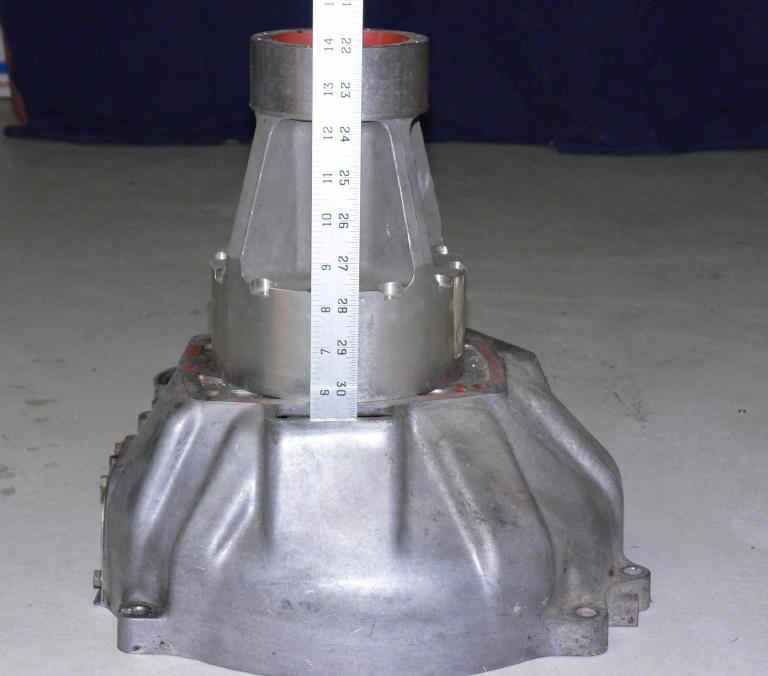
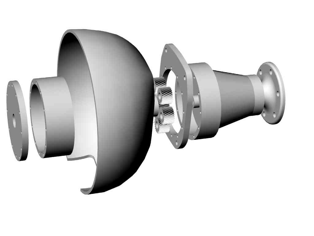
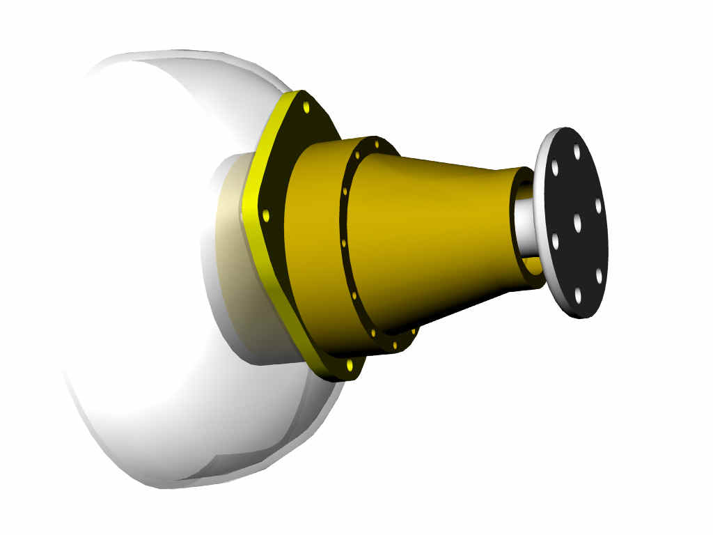
We should look into a spun or pressed bell housing and use the two hollow
dowel pins on the end housing to locate the unit more accurately. Along
with a lighter weight gear box of course :) The bolt and spacer idea is
less than ideal.
Paul Lamar
--
Hi Paul,
Before you open up ALL the 10 mm holes bear in mind that Tracey uses them
as a final drive alignment device.
Refer to his instruction sheets where he mentions if there is drag or
binding of the hand rotated prop flange the
user should loosen the bolts and tap the plate, retighten the bolts
and check again. A less than ideal situation,
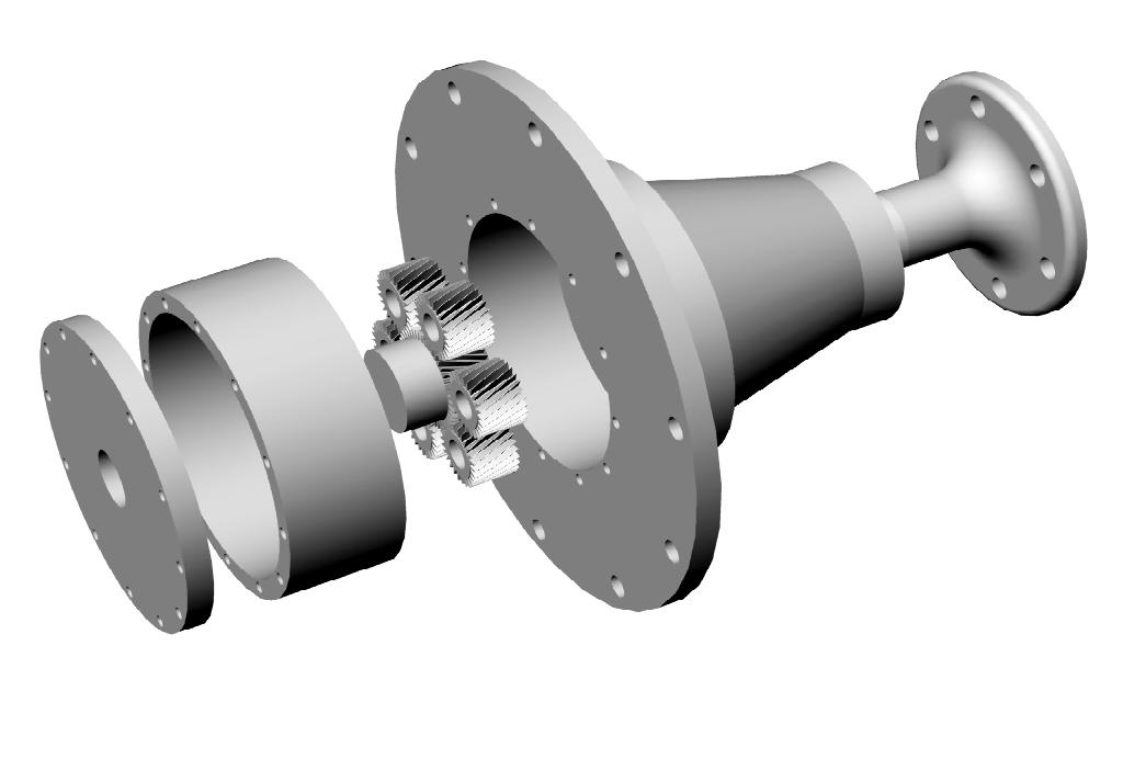
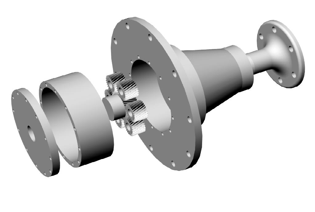
but it does seem to work. This final drive assembly may be a place
where you should get creative and devise a positive way to
transfer the 2 hollow dowel locations thru the standoffs and into
the MM plate and also provide either dowel pins
or a closely toleranced g'box boss / MM plate bore. The boss/bore is
probably perferable since it's one toleranced
relationship instead of four required by dowel pins. Rotationally
the g'box can index anywhere on it's bolt pattern,
at least until you add the governor mounting pad ; ) Dave M
Yes I am aware Tracy uses the holes as alignment devices unfortunately.
But .7 MM is not going to affect that on average.
I don't want to get in the position of fixing his design.
We have been around and around on a bell housing casting
to locate his gearbox but so far we have not been able
to come up with a light weight low cost solution.
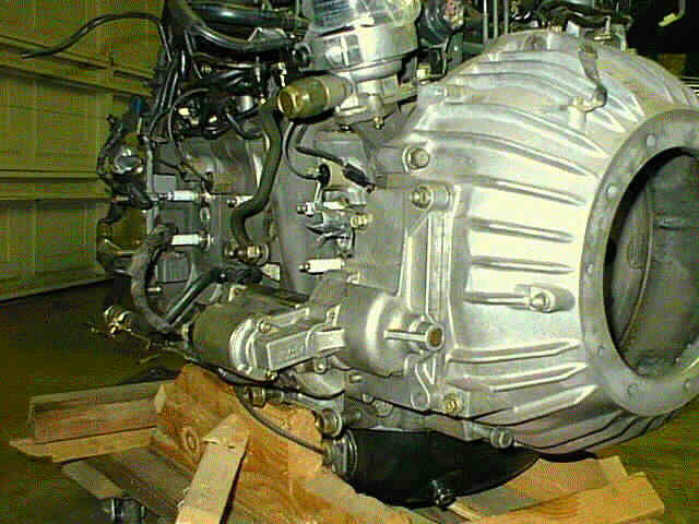
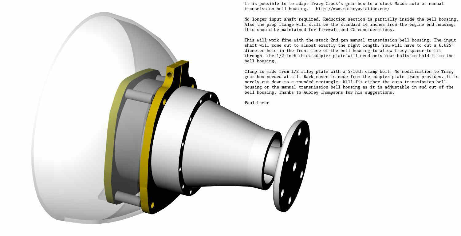
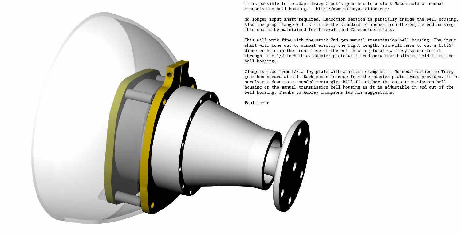
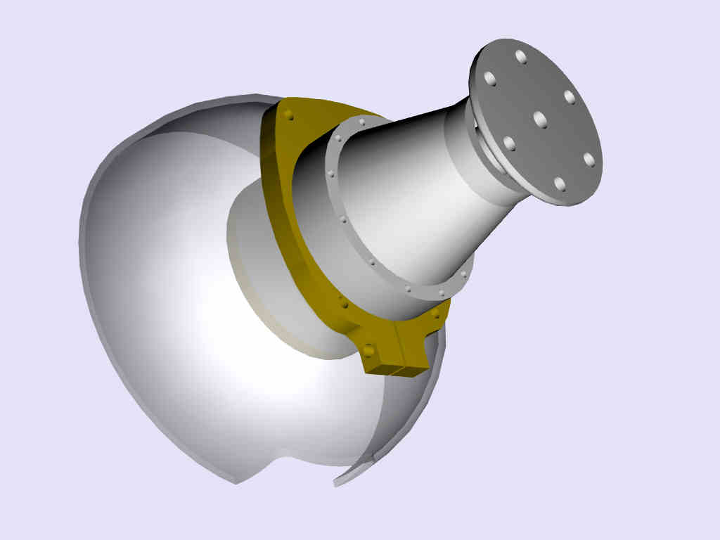
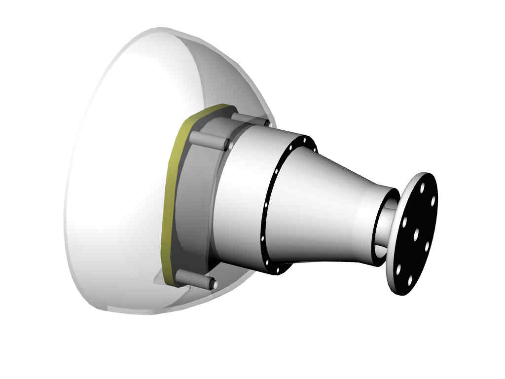
The best bet is to use a Mazda bell housing and adapt
Tracy box to that if you are concerned as some have done already.
Paul Lamar
--
The Rotary Engine NewsLetter. Powered by Linux.
ACRE NL web site.
http://www.rotaryeng.net
Youtube key word UTUBPLEASE
Copyright 1998-2009 All world wide rights reserved.